Key Takeaway
Complete 3 phase cable size chart with current ratings for 3-core, 3+1, 3+2 configurations from 1.5mm² to 800mm². Includes motor sizing, voltage drop calculations, IEC/BS/NFC standards by region, and copper vs aluminium comparison. Factory direct pricing available.
Three-phase power cable carries the bulk of the world's electrical energy from substations to factories, commercial buildings, pump stations, and motor drives. Whether you are wiring a 30kW motor, feeding a distribution board, or running a kilometre of underground trunk line to a new development, selecting the correct 3 phase cable configuration — 3-core, 3+1 core, or 3+2 core — determines the safety, efficiency, and cost of your installation.
This guide gives procurement engineers, electrical contractors, and EPC project managers the full technical picture: conductor sizing from 1.5mm² to 800mm², voltage class options, insulation and sheath materials, IEC and national standard references, current ratings, and what to check when sourcing from a cable factory in China.
We manufacture 3 phase power cables at our facility in Henan, China — certified to IEC 60502-1, IEC 60502-2, and GB/T 12706.
What Is 3 Phase Power Cable?
A 3 phase power cable contains three power conductors — one for each phase of an alternating current system (L1, L2, L3). The three conductors are laid up together inside a common outer sheath, and may include additional smaller conductors for neutral and/or earth continuity.
Three-phase systems are the standard for:
- Industrial machinery and motor drives (above 2kW)
- Commercial building main feeders
- Underground distribution networks
- Pump stations, HVAC systems, and elevator supplies
- Data centres and large-scale solar inverter connections
The key advantage over single-core cables: a single 3 phase cable replaces three separate runs, reducing installation labour, duct space, and material cost.
Core Configurations
| Configuration | Conductors | Typical Use |
|---|---|---|
| 3-core (3C) | L1 + L2 + L3 | Motor feeds where earth is via separate conductor or metallic conduit |
| 3+1 core (3C+E or 3C+N) | L1 + L2 + L3 + reduced neutral or earth | Distribution circuits where combined neutral/earth is acceptable |
| 3+2 core (3C+N+E) | L1 + L2 + L3 + full neutral + earth | Main feeders requiring separate neutral and earth per IEC 60364 |
| 3×1C (single-core trefoil) | 3 separate single-core cables | High-current circuits above 300mm² where single-core is more practical |
When to Choose Each Configuration
3-core: Most motor circuits. Motors don't require a neutral — just three phases. The earthing conductor is typically the cable armour (SWA) or a separate earth wire.
3+1 core: The most common choice for distribution. The fourth conductor serves as a combined neutral-earth (PEN) in TN-C systems, or as a reduced neutral where harmonic currents are low. The neutral conductor is typically half the cross-section of the phase conductors (e.g., 3×70+35mm²).
3+2 core: Required where regulations mandate separate neutral and earth conductors (TN-S systems). Common in IEC markets for main incoming supplies. Both the neutral and earth conductors may be full-size or reduced depending on the design.
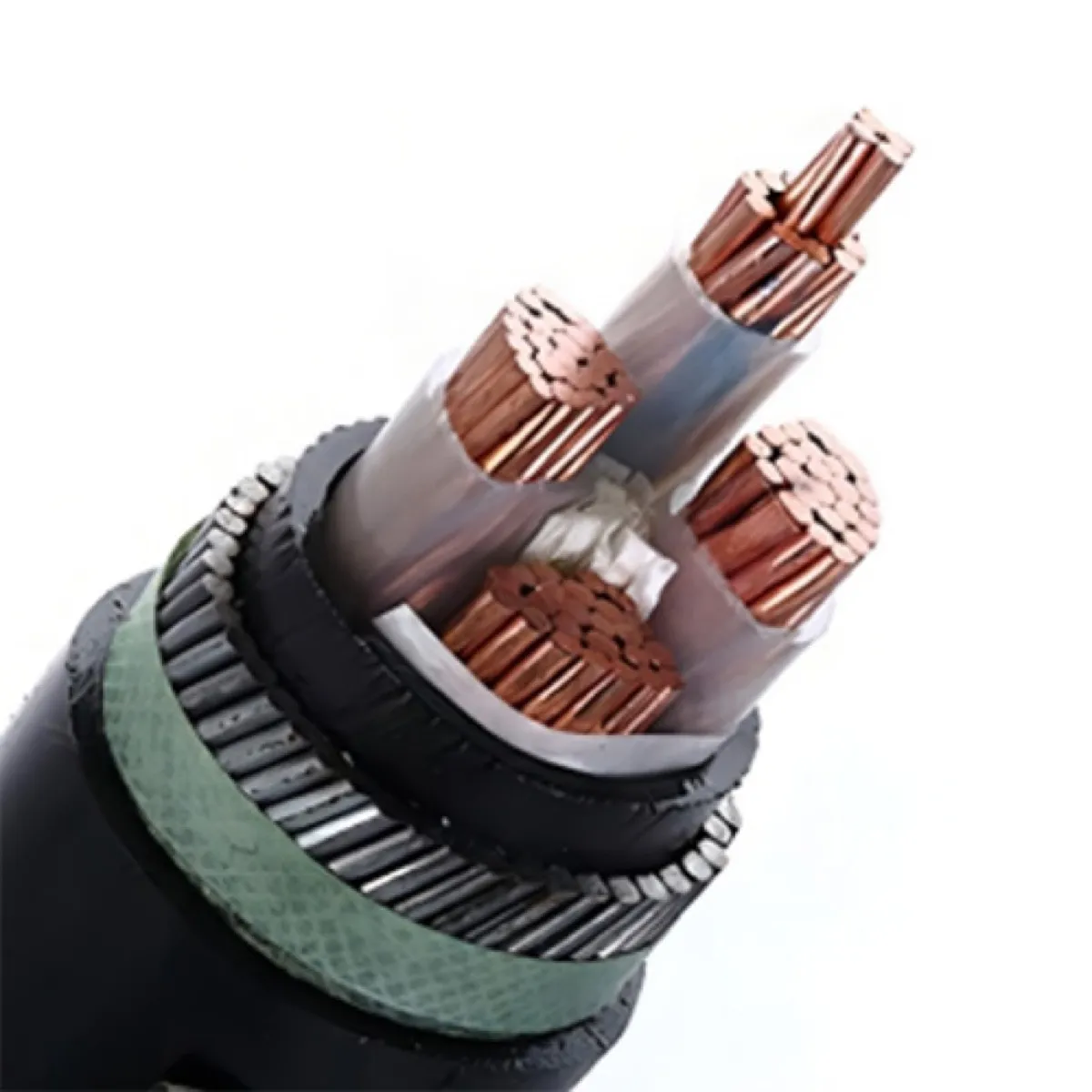
3 Phase Cable Construction
Layer-by-Layer Construction
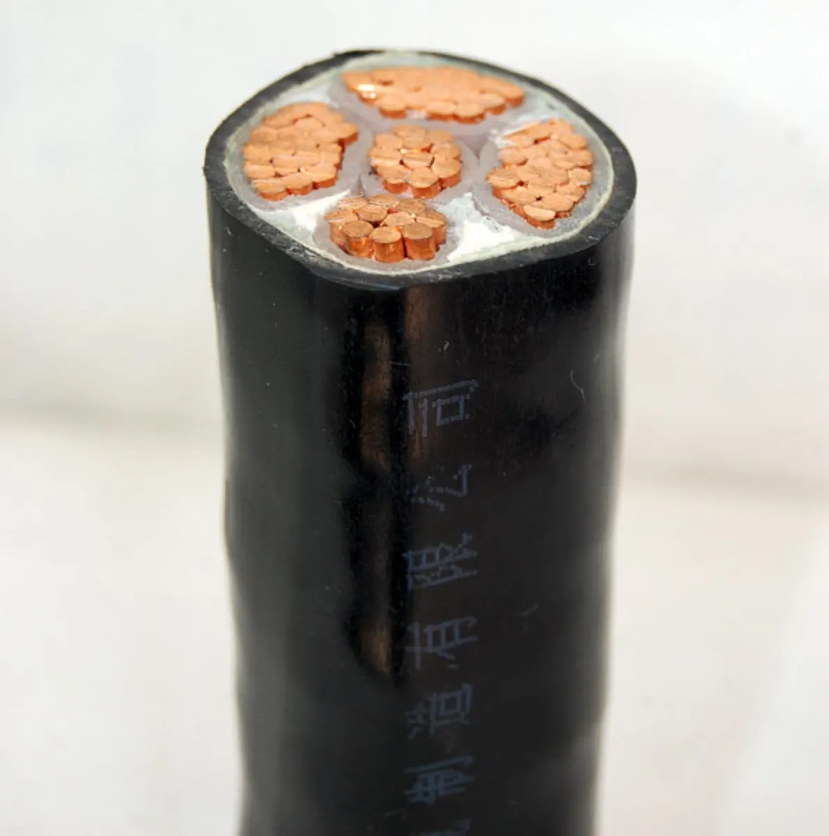
1. Conductor
- Material: Copper (Cu) Class 1 or Class 2, or Aluminium (Al) Class 1 or Class 2 per IEC 60228
- Shape: Circular for sizes up to 25mm²; sector-shaped for 50mm² and above (reduces overall cable diameter)
- Class 1: Solid conductor (single wire) — used up to 6mm²
- Class 2: Stranded conductor — standard for 10mm² and above
- Class 5: Flexible stranded conductor — used for flexible power cables and frequent movement applications
2. Insulation
- XLPE (Cross-Linked Polyethylene): Maximum conductor temperature 90°C, short-circuit 250°C. Standard for modern installations.
- PVC: Maximum conductor temperature 70°C, short-circuit 160°C. Lower cost, adequate for less demanding circuits.
- EPR (Ethylene Propylene Rubber): Maximum conductor temperature 90°C. Flexible, used in special applications.
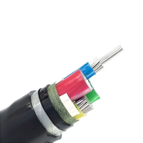
3. Core Identification
- Colour coding per IEC 60446: Brown (L1), Black (L2), Grey (L3), Blue (Neutral), Green-Yellow (Earth)
- Or numbered cores with printed identification
4. Inner Sheath (Bedding)
- PVC or low-smoke zero-halogen (LSZH) compound
- Provides a smooth bed for the armour layer
- Fills interstices between cores
5. Armour (optional but standard for underground/industrial)
- SWA (Steel Wire Armour): Round galvanized steel wires. Standard for multi-core cables. Provides mechanical protection and can serve as earth continuity conductor.
- STA (Steel Tape Armour): Two helically-wound steel tapes. Lighter than SWA, adequate for direct burial where longitudinal force is minimal. See our underground power cable installation guide for burial depth and duct requirements.
- AWA (Aluminium Wire Armour): Non-magnetic. Required for single-core cables to avoid eddy current heating.
6. Outer Sheath
- PVC: Standard, robust, UV-resistant with carbon black additive
- PE (Polyethylene): Better moisture resistance for underwater or high-humidity
- LSZH: Mandatory in enclosed public spaces (metro, tunnels, airports) per IEC 60332-3. See our fire resistant cable range for circuit integrity applications.
Sector-Shaped vs Round Conductors
For 3 phase cables 50mm² and above, sector-shaped (also called shaped or segmental) conductors are standard. The advantage:
- Overall cable diameter reduced by 15–20% compared to round conductors
- Less material used in fillers and sheath
- Lower cable weight per metre
- Smaller bending radius
- Reduced duct space requirement
For example, a 3×185mm² cable with sector-shaped conductors has approximately the same outer diameter as a 3×120mm² cable with round conductors.
Voltage Ratings and Designations
3 phase power cables are manufactured for different voltage classes:
| Voltage Rating (Uo/U) | System Voltage | Application |
|---|---|---|
| 0.6/1kV | Up to 1kV | Low-voltage distribution, motor feeds, building wiring |
| 1.8/3kV | 3.3kV | Industrial medium-voltage motors |
| 3.6/6kV | 6.6kV | Primary distribution, large motors |
| 6/10kV | 11kV | Urban underground distribution |
| 8.7/15kV | 13.8–15kV | Utility distribution (Americas) |
| 12/20kV | 22kV | Distribution networks |
| 18/30kV | 33kV | Sub-transmission |
| 26/35kV | 40.5kV | Sub-transmission and industrial supply |
Where Uo = rated voltage between conductor and earth, U = rated voltage between conductors.
Type Designation Codes
Different standards use different naming conventions:
IEC/Chinese (GB/T 12706):
- YJV: XLPE insulated, PVC sheathed (unarmoured)
- YJV22: XLPE insulated, steel tape armoured, PVC sheathed
- YJV32: XLPE insulated, steel wire armoured, PVC sheathed
- VV: PVC insulated, PVC sheathed
- VV22: PVC insulated, steel tape armoured, PVC sheathed
British (BS 5467/BS 6724):
- 6946: PVC/SWA/PVC
- 5467: XLPE/SWA/PVC
- 6724: XLPE/SWA/LSZH
Example designation: YJV32 3×120+1×70mm² 0.6/1kV = 3 phase XLPE insulated, steel wire armoured, PVC sheathed cable, 120mm² phase conductors with 70mm² neutral, rated 0.6/1kV.
3 Phase Cable Sizes: Complete Specification Tables
0.6/1kV XLPE Insulated 3-Core Cable (IEC 60502-1 / GB/T 12706.1)
| Size (mm²) | Conductor Stranding | Insulation Thickness (mm) | Approx. OD (mm) | Approx. Weight (kg/km) |
|---|---|---|---|---|
| 3×1.5 | 7/0.52 | 0.7 | 12.5 | 185 |
| 3×2.5 | 7/0.67 | 0.7 | 13.5 | 240 |
| 3×4 | 7/0.85 | 0.7 | 14.8 | 320 |
| 3×6 | 7/1.04 | 0.7 | 15.8 | 395 |
| 3×10 | 7/1.35 | 0.7 | 18.0 | 545 |
| 3×16 | 7/1.70 | 0.7 | 20.0 | 740 |
| 3×25 | 7/2.14 | 0.9 | 24.5 | 1,080 |
| 3×35 | 7/2.52 | 0.9 | 27.0 | 1,380 |
| 3×50 | 19/1.83 | 1.0 | 30.5 | 1,800 |
| 3×70 | 19/2.14 | 1.1 | 34.5 | 2,450 |
| 3×95 | 19/2.52 | 1.1 | 38.5 | 3,200 |
| 3×120 | 37/2.03 | 1.2 | 42.0 | 3,950 |
| 3×150 | 37/2.25 | 1.4 | 46.0 | 4,850 |
| 3×185 | 37/2.52 | 1.6 | 50.5 | 5,950 |
| 3×240 | 61/2.25 | 1.7 | 56.5 | 7,650 |
| 3×300 | 61/2.52 | 1.8 | 62.0 | 9,500 |
| 3×400 | 61/2.89 | 2.0 | 69.0 | 12,000 |
| 3×500 | 61/3.23 | 2.2 | 76.0 | 15,000 |
| 3×630 | 91/2.97 | 2.4 | 85.0 | 18,800 |
| 3×800 | 91/3.33 | 2.6 | 93.0 | 23,500 |
Note: Dimensions are for unarmoured cable with round stranded copper conductors. Armoured versions add approximately 5–8mm to diameter and 20–35% to weight depending on armour type.
0.6/1kV XLPE Insulated 3+1 Core Cable (Phase + Reduced Neutral)
| Size (mm²) | Neutral Size (mm²) | Approx. OD (mm) | Approx. Weight (kg/km) |
|---|---|---|---|
| 3×10+1×6 | 6 | 20.5 | 620 |
| 3×16+1×10 | 10 | 22.5 | 850 |
| 3×25+1×16 | 16 | 27.5 | 1,250 |
| 3×35+1×16 | 16 | 29.5 | 1,550 |
| 3×50+1×25 | 25 | 33.5 | 2,100 |
| 3×70+1×35 | 35 | 38.0 | 2,850 |
| 3×95+1×50 | 50 | 42.5 | 3,700 |
| 3×120+1×70 | 70 | 47.0 | 4,650 |
| 3×150+1×70 | 70 | 50.5 | 5,550 |
| 3×185+1×95 | 95 | 55.5 | 6,900 |
| 3×240+1×120 | 120 | 62.0 | 8,900 |
| 3×300+1×150 | 150 | 68.0 | 11,000 |
| 3×400+1×185 | 185 | 75.0 | 13,800 |
Current Carrying Capacity (Ampacity)
Current ratings for 3-core XLPE insulated copper cable, laid direct in ground at 20°C soil temperature, 1.0 K·m/W soil thermal resistivity, burial depth 0.8m (per IEC 60287):
| Size (mm²) | Direct Buried (A) | In Duct (A) | In Air (A) |
|---|---|---|---|
| 1.5 | 26 | 22 | 22 |
| 2.5 | 35 | 30 | 30 |
| 4 | 46 | 39 | 40 |
| 6 | 58 | 49 | 51 |
| 10 | 79 | 66 | 70 |
| 16 | 104 | 87 | 94 |
| 25 | 138 | 114 | 119 |
| 35 | 164 | 136 | 148 |
| 50 | 197 | 163 | 180 |
| 70 | 245 | 201 | 226 |
| 95 | 292 | 240 | 271 |
| 120 | 334 | 275 | 312 |
| 150 | 375 | 308 | 352 |
| 185 | 424 | 348 | 399 |
| 240 | 492 | 403 | 468 |
| 300 | 558 | 457 | 533 |
| 400 | 640 | 525 | 600 |
| 500 | 730 | 597 | 680 |
| 630 | 825 | 675 | 770 |
| 800 | 935 | 765 | 870 |
Derating factors to apply:
| Condition | Factor |
|---|---|
| Soil temperature 25°C | 0.96 |
| Soil temperature 30°C | 0.93 |
| Soil temperature 35°C | 0.89 |
| Soil resistivity 1.5 K·m/W | 0.89 |
| Soil resistivity 2.0 K·m/W | 0.81 |
| Depth 1.0m (instead of 0.8m) | 0.97 |
| Two circuits touching | 0.80 |
| Three circuits touching | 0.70 |
| Ambient air 40°C (in air) | 0.91 |
| Ambient air 50°C (in air) | 0.82 |
Selecting the Right 3 Phase Cable Size
Step-by-Step Sizing Method
Cable sizing for a three-phase circuit follows this sequence (for a comprehensive reference covering all conductor sizes and installation methods, see our cable size chart with mm² to AWG conversion and ampacity tables):
Step 1: Determine the full-load current
For a three-phase load:
- I = P / (√3 × V × cosφ)
- Where P = power in watts, V = line voltage, cosφ = power factor
Example: A 90kW motor at 400V, power factor 0.85:
- I = 90,000 / (1.732 × 400 × 0.85) = 153A
Step 2: Apply diversity and future growth factors
Standard practice: add 20–25% margin for future load growth unless the circuit is for a dedicated motor (where starting current is the concern, not growth).
Step 3: Select cable size from ampacity table
From the table above (direct buried): 153A falls between 120mm² (334A — more than adequate) and 95mm² (292A). However, you must also check voltage drop.
Step 4: Verify voltage drop
Maximum allowable voltage drop per IEC 60364: 4% for final circuits, 2% for distribution circuits in most national standards. Some countries allow 5% total.
Three-phase voltage drop formula:
- ΔV = (√3 × I × L × (R·cosφ + X·sinφ)) / 1000
- Where L = cable length in metres, R = resistance in mΩ/m, X = reactance in mΩ/m
Step 5: Verify short-circuit withstand
The cable must withstand the prospective short-circuit current for the disconnection time of the protective device:
- Minimum size = I²t / k²
- Where k = 143 for XLPE/copper, 94 for XLPE/aluminium
Common Motor Ratings and Recommended Cable Sizes
| Motor Rating | Voltage | Approx. FLC (A) | Recommended Cable (Cu) | Recommended Cable (Al) |
|---|---|---|---|---|
| 5.5kW | 400V | 11.5 | 3×2.5mm² | 3×4mm² |
| 7.5kW | 400V | 15.5 | 3×2.5mm² | 3×4mm² |
| 11kW | 400V | 22.5 | 3×4mm² | 3×6mm² |
| 15kW | 400V | 30 | 3×6mm² | 3×10mm² |
| 22kW | 400V | 43 | 3×10mm² | 3×16mm² |
| 30kW | 400V | 58 | 3×16mm² | 3×25mm² |
| 37kW | 400V | 72 | 3×25mm² | 3×35mm² |
| 45kW | 400V | 87 | 3×25mm² | 3×50mm² |
| 55kW | 400V | 106 | 3×35mm² | 3×50mm² |
| 75kW | 400V | 144 | 3×50mm² | 3×95mm² |
| 90kW | 400V | 170 | 3×70mm² | 3×120mm² |
| 110kW | 400V | 210 | 3×95mm² | 3×150mm² |
| 132kW | 400V | 250 | 3×120mm² | 3×185mm² |
| 160kW | 400V | 300 | 3×150mm² | 3×240mm² |
| 200kW | 400V | 375 | 3×185mm² | 3×300mm² |
| 250kW | 400V | 465 | 3×240mm² | 3×400mm² |
| 315kW | 400V | 585 | 3×300mm² | 3×500mm² |
| 400kW | 400V | 740 | 3×400mm² | 3×630mm² |
| 500kW | 400V | 920 | 3×500mm² | 3×800mm² |
Note: Cable sizes assume short run lengths. For runs exceeding 50m, perform a voltage drop calculation — you may need to upsize.
Installation Methods for 3 Phase Underground Cable
Direct Burial
The most cost-effective method for underground 3 phase cable runs:
- Trench depth: Minimum 600mm cover for cables up to 1kV, 800mm for medium voltage (varies by national code)
- Sand bedding: 75mm sand or fine soil below and 75mm above the cable
- Mechanical protection: Cable cover tiles, concrete slabs, or warning tape at 300mm above cable
- Separation: Minimum 150mm between parallel circuits; 300mm from other services (water, gas)
- Cable type: SWA (steel wire armoured) mandatory for direct burial
- Thermal backfill: If native soil has poor thermal resistivity, use controlled thermal backfill (cement-bound sand) around cables
In Ducts
Used where future access is required or in urban areas with congested underground services:
- Duct material: uPVC, HDPE, or concrete — minimum 100mm internal diameter for single cable
- Fill ratio: Cable OD should not exceed 45% of duct ID for easy pulling
- Pulling force: Calculate maximum sidewall pressure for long runs — consider intermediate manholes for routes exceeding 100m with bends
- Derating: Cables in ducts carry less current than direct buried (see ampacity table above)
In Cable Tray (Indoor)
For industrial facilities where cables run on steel tray or ladder:
- Spacing: Maintain at least one cable diameter spacing between multi-core cables on tray for thermal derating purposes
- Fixing: Cleats at maximum 600mm centres for cables on vertical runs
- Fire barriers: Penetration seals where cables pass through fire-rated walls
- Arrangement: Trefoil touching arrangement for single-core 3 phase cables to balance reactance
Bending Radius
Minimum bending radius for 3 phase power cables:
| Cable Type | Minimum Bend Radius |
|---|---|
| Unarmoured, up to 25mm OD | 6× cable OD |
| Unarmoured, above 25mm OD | 8× cable OD |
| SWA armoured | 8× cable OD |
| STA armoured | 8× cable OD |
| Single-core, armoured | 12× cable OD |
| Medium voltage (screened) | 12× cable OD |
Medium Voltage 3 Phase Cable (6kV to 33kV)
For voltage levels above 1kV, 3 phase cable construction becomes more complex with the addition of semi-conductive screens and metallic sheaths. Our medium voltage cable guide covering 11kV and 33kV specifications provides detailed construction breakdowns and sizing tables for MV applications:
Construction Differences from LV Cable
| Layer | LV Cable (0.6/1kV) | MV Cable (6/10kV+) |
|---|---|---|
| Conductor screen | Not required | Semi-conductive layer (extruded) |
| Insulation | 0.7–2.4mm XLPE | 3.4–8.0mm XLPE |
| Insulation screen | Not required | Semi-conductive layer (extruded) |
| Metallic screen | Not required | Copper tape or wire screen |
| Water blocking | Not standard | Swellable tapes or powder (optional) |
MV 3 Phase Cable Specifications (per IEC 60502-2)
| Voltage | Insulation Thickness (mm) | Conductor Screen (mm) | Insulation Screen (mm) |
|---|---|---|---|
| 3.6/6kV | 3.4 | 0.5 | 0.5 |
| 6/10kV | 3.4 | 0.5 | 0.5 |
| 8.7/15kV | 4.5 | 0.5 | 0.5 |
| 12/20kV | 5.5 | 0.7 | 0.7 |
| 18/30kV | 8.0 | 1.0 | 1.0 |
3-Core vs Single-Core at Medium Voltage
For MV applications, the choice between 3-core and single-core depends on conductor size:
- Up to 300mm²: 3-core cable is standard. More economical and easier to install than three single-cores.
- Above 300mm²: Single-core becomes necessary because the overall 3-core cable diameter and weight become impractical for handling and installation.
- Above 630mm² at 11kV+: Always single-core.
The crossover point varies by voltage level — at 33kV, 3-core cables are typically limited to 185mm² maximum due to the thick insulation.
Copper vs Aluminium Conductor: Which to Specify
This is one of the most frequent decisions buyers face. Here's how to evaluate:
Technical Comparison
| Property | Copper | Aluminium |
|---|---|---|
| Conductivity (% IACS) | 100 | 61 |
| Equivalent size for same current | 1× | 1.6× |
| Density (kg/m³) | 8,890 | 2,700 |
| Weight for equivalent current | 1× | 0.48× |
| Tensile strength | Higher | Lower |
| Corrosion resistance | Excellent | Good (oxide layer protects) |
| Ease of termination | Easy | Requires anti-oxidant and correct lugs |
| Short-circuit k factor (XLPE) | 143 | 94 |
When to Choose Copper
- Space-constrained installations (smaller cable diameter for same current)
- Subsea or high-corrosion environments
- Frequent disconnection/reconnection expected
- Short-circuit levels are high (copper withstands more I²t per mm²)
- Customer specification requires copper
When to Choose Aluminium
- Long cable runs where weight matters for installation
- Cost is the primary driver (aluminium is typically less expensive for equivalent current capacity)
- Overhead-fed installations where cable weight loads supports
- Large cross-sections (300mm²+) where the size difference is acceptable
Size Equivalency Table
| Required Current (A) | Copper Size | Aluminium Size |
|---|---|---|
| 70 | 10mm² | 16mm² |
| 94 | 16mm² | 25mm² |
| 119 | 25mm² | 35mm² |
| 148 | 35mm² | 50mm² |
| 180 | 50mm² | 70mm² |
| 226 | 70mm² | 95mm² |
| 271 | 95mm² | 150mm² |
| 312 | 120mm² | 185mm² |
| 352 | 150mm² | 240mm² |
| 399 | 185mm² | 300mm² |
Standards and Testing Requirements
International Standards
| Standard | Scope |
|---|---|
| IEC 60502-1 | Power cables 1kV to 3kV — construction, dimensions, testing |
| IEC 60502-2 | Power cables 6kV to 30kV |
| IEC 60228 | Conductor specification (classes 1, 2, 5, 6) |
| IEC 60287 | Current rating calculations |
| IEC 60332-1 | Single cable flame propagation test |
| IEC 60332-3 | Bunched cable flame propagation test |
| IEC 60811 | Methods for testing non-metallic materials |
National Standards
| Country/Region | LV Cable Standard | MV Cable Standard |
|---|---|---|
| China | GB/T 12706.1 | GB/T 12706.2/3 |
| UK/Commonwealth | BS 5467, BS 6724 | BS 6622, BS 7835 |
| France | NFC 32-321 | NFC 33-226 |
| Germany | VDE 0276-603 | VDE 0276-620 |
| Australia | AS/NZS 5000.1 | AS/NZS 1429.1 |
| USA | UL 1072, ICEA S-93-639 | ICEA S-94-649 |
| South Africa | SANS 1507 | SANS 1339 |
Which Standard Applies to Your Market?
Selecting the correct cable standard is critical — using the wrong standard can delay customs clearance, fail inspection, or void project warranties. Here is what applies by region:
South Asia (Pakistan, Bangladesh, India, Sri Lanka): IEC 60502 is the primary reference. Pakistan's WAPDA and most private sector EPC contractors specify cables to IEC 60502-1 (LV) and IEC 60502-2 (MV). India accepts both IS 7098 (which mirrors IEC 60502) and direct IEC compliance. Bangladesh follows IEC standards for utility-scale projects. Conductor sizes follow the metric IEC 60228 series (1.5, 2.5, 4, 6, 10, 16, 25... up to 1000mm²).
Southeast Asia (Vietnam, Philippines, Indonesia, Malaysia): Vietnam's EVN (Electricity of Vietnam) specifies IEC 60502 for all power cable procurement. The Philippines follows IEC with Philippine Electrical Code (PEC) overlay. Indonesia uses SNI standards (based on IEC). Malaysia references BS and IEC depending on the utility — TNB historically used BS but is transitioning to IEC for new projects.
Middle East (Saudi Arabia, UAE, Iraq, Jordan): Saudi Arabia requires SASO (Saudi Standards) certification, but the technical standard is IEC 60502 with additional testing requirements including hot sand burial tests. UAE follows ADDC/DEWA specifications which reference IEC and BS. Iraq follows IEC standards. Jordan uses IEC 60502 directly.
Africa (South Africa, Nigeria, Kenya, East Africa): South Africa has its own SANS standards (SANS 1507 for LV, SANS 1339 for MV) — these are technically aligned with IEC but have additional requirements for local conditions. Nigeria accepts both BS and IEC. East Africa (Kenya, Tanzania, Uganda) primarily follows BS/IEC hybrid standards.
Latin America (Brazil, Mexico, Colombia, Argentina): Brazil uses ABNT NBR standards (NBR 7286/7287) which are IEC-based but with Portuguese documentation requirements. Mexico follows NOM standards (NOM-063-SCFI for LV). Colombia and Argentina follow IEC 60502 directly.
UK and Commonwealth (UK, Australia, New Zealand): The UK uses BS 5467 (XLPE/SWA/PVC) and BS 6724 (XLPE/SWA/LSZH) for LV, BS 6622 for MV. Australia uses AS/NZS 5000.1 (LV) and AS/NZS 1429.1 (MV) — similar to IEC but with specific Australian requirements for termite resistance and UV exposure.
Practical tip for buyers: If your project specification simply says "IEC 60502" without further national requirements, the cable can be manufactured to pure IEC standard. If it references a national standard (SASO, SANS, NOM), confirm the additional test requirements before production — they often add cost and lead time. Our factory produces to all major standards listed above and holds relevant type test reports for each.
Factory Testing (Routine Tests per IEC 60502)
Every drum of cable produced undergoes these tests before shipment:
- Conductor resistance: Measured at 20°C, must be within IEC 60228 limits
- High-voltage test (HV): Applied voltage for specified duration without breakdown
- 0.6/1kV cable: 3.5kV AC for 5 minutes
- 6/10kV cable: 21kV AC for 5 minutes
- Insulation resistance: Measured at 500V DC (LV) or 2500V DC (MV), minimum values per standard
- Partial discharge test (MV only): Maximum 10pC at 1.73× Uo
Type Tests
Performed on representative samples to validate the cable design:
- Bending test followed by partial discharge measurement
- Tan delta (dissipation factor) measurement
- Impulse withstand voltage (BIL)
- 4-hour voltage test at elevated temperature
- Shrinkage test on insulation
- Hot set test on XLPE (verifies cross-linking degree)
Quality Verification for Buyers
When sourcing 3 phase cable from any manufacturer — whether from one of the top 10 XLPE cable manufacturers in China or elsewhere — verify these critical points:
Before Ordering
- Request the IEC type test report for the specific cable design you are ordering. A legitimate manufacturer will have this on file.
- Check certifications: ISO 9001 (quality management), ISO 14001 (environmental), and product certifications relevant to the destination country (KEMA, CCC, CB scheme, SABS, etc.)
- Ask for conductor source: The quality of copper or aluminium rod directly affects conductor resistance and flexibility.
- Request a factory visit or third-party audit for orders above a significant value.
During Production
- Request witness testing: Attend or assign a third-party to witness routine electrical tests on your production drums
- Verify conductor resistance: This single measurement confirms copper purity and conductor cross-section simultaneously
- Check insulation thickness: Must meet minimum values per standard at all points around circumference
- Verify armour wire diameter and galvanizing: Sub-standard armour is a common cost-cutting area
Before Shipment
- Request test certificates: Full routine test results for every drum, including drum number, cable length, and test values
- Check marking: Cable should be permanently marked with manufacturer name, voltage rating, core configuration, conductor size, standard, and metre marks
- Verify packaging: Steel drums for armoured export cable; wooden drums acceptable for lighter cables if properly protected
Applications by Industry
Power Distribution and Utilities
Underground distribution networks are the largest consumer of 3 phase power cable globally. Typical configurations:
- 11kV ring main: 3×185mm² or 3×240mm² XLPE/SWA, connecting ring main units (RMUs). See our 11kV cable specifications & size chart for complete current rating tables.. See our 11kV cable size chart and current rating tables for complete MV sizing data.
- LV distribution: 3×300+150mm² or 4×300mm² from transformer to distribution pillars
- Service connections: 3×25+16mm² or 3×35+16mm² from pillar to customer intake
Industrial Facilities
- Motor feeds: 3-core SWA cable from MCC (Motor Control Centre) to each motor
- Bus duct alternatives: Large 3 phase cables (3×400mm²+) where bus duct is too expensive or impractical
- Emergency generator feeds: Often require fire-resistant (FR) cable with 3-hour circuit integrity
Commercial Buildings
- Main intake: 3+1 or 3+2 core SWA from utility transformer to main switchboard
- Riser cables: Vertical runs feeding floor distribution boards
- Mechanical services: Dedicated 3 phase feeds to chillers, pumps, lifts
Renewable Energy
- Solar farms: 3-core cables from inverters to MV transformer; MV 3-core cables from transformer to grid connection
- Wind farms: MV 3-core cables from turbine base to collection point (often 33kV)
LSZH (Low Smoke Zero Halogen) 3 Phase Cable
For installations in enclosed spaces where people may be present during a fire:
When LSZH Is Required
- Public buildings (shopping centres, airports, hospitals)
- Underground railway and metro systems
- Road tunnels and enclosed car parks
- Ships and offshore platforms
- Data centres
LSZH vs PVC Properties
| Property | PVC Sheath | LSZH Sheath |
|---|---|---|
| Smoke density (IEC 61034) | High | Low (passes IEC 61034) |
| Halogen content | High (HCl released in fire) | Zero |
| Flame propagation (IEC 60332-3) | Category C | Category C or better |
| Water absorption | Low | Higher than PVC |
| Mechanical toughness | Good | Slightly lower |
| UV resistance | Good (with carbon black) | Requires additives |
Standard Equivalents
| PVC Cable | LSZH Equivalent |
|---|---|
| BS 5467 (XLPE/SWA/PVC) | BS 6724 (XLPE/SWA/LSZH) |
| YJV22 (China, PVC sheath) | WDZYJY23 (China, LSZH sheath) |
Fire-Resistant 3 Phase Cable
Distinct from LSZH (which limits smoke/halogen), fire-resistant cable maintains circuit integrity during a fire:
- IEC 60331: Cable must continue to function for 90 minutes at 750°C (or 180 minutes for critical circuits)
- BS 8519: Specifies enhanced fire-resistant cables for life-safety systems
- Applications: Fire pump feeds, emergency lighting, fire alarm circuits, smoke extraction fans, emergency lift supplies
Construction: Additional mica tape wrapping around each conductor provides the fire barrier. The mica tape withstands temperatures above 1000°C, maintaining electrical insulation even after the XLPE has decomposed.
How to Specify 3 Phase Cable for Your Project
When requesting a quotation, provide:
- Voltage rating (e.g., 0.6/1kV, 6/10kV, 12/20kV)
- Core configuration (3C, 3+1C, 3+2C)
- Conductor material (copper or aluminium)
- Conductor size (mm²) — or state the load current and let us recommend
- Insulation type (XLPE or PVC)
- Armour type (SWA, STA, unarmoured)
- Outer sheath (PVC, PE, LSZH)
- Applicable standard (IEC, BS, GB, NFC, etc.)
- Total quantity (metres or kilometres)
- Number of lengths per drum (standard or custom)
- Destination and incoterm (FOB, CIF, etc.)
The more complete your specification, the faster and more accurate the quotation.
Our Manufacturing Capability
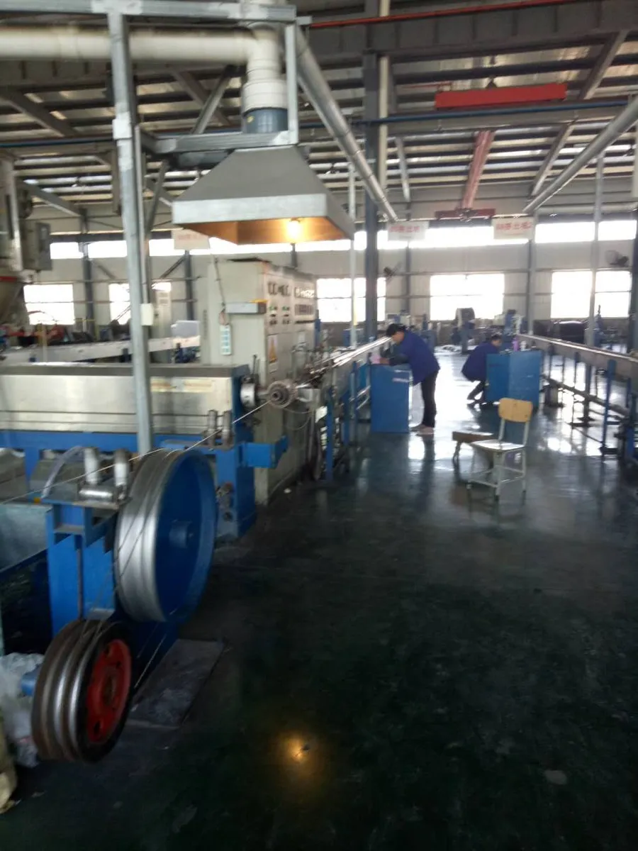
Our factory produces 3 phase power cable across the full range. See our factory page for equipment and certification details.
- Voltage range: 0.6/1kV to 35kV
- Conductor sizes: 1.5mm² to 800mm² (copper and aluminium)
- All configurations: 3C, 3+1C, 3+2C, and single-core for trefoil installation
- Armour options: SWA, STA, AWA, or unarmoured
- Sheath options: PVC, PE, LSZH
- Standards: IEC 60502, GB/T 12706, BS 5467/6724, NFC 33-226, AS/NZS 5000
Equipment
- CCV (Catenary Continuous Vulcanization) lines for XLPE cross-linking
- VCV (Vertical Continuous Vulcanization) for medium and high voltage cable
- Sector-shaping compacting dies for 35mm² and above
- Automatic stranding machines for copper and aluminium conductors
- Steel wire armouring machines for SWA production
- Full-scale high-voltage test facility up to 200kV AC and 400kV DC
Frequently Asked Questions
What is the difference between 3-core and 3+1 core cable?
A 3-core cable has only three phase conductors (L1, L2, L3). A 3+1 core cable adds a fourth conductor — typically smaller than the phase conductors — used as either a neutral (for unbalanced loads) or as an earth continuity conductor. For motor circuits where no neutral is needed, 3-core is sufficient. For distribution circuits feeding mixed single-phase and three-phase loads, 3+1 is the standard choice.
Can I use 3 phase cable for single-phase supply?
Yes. You can use two cores for live and neutral, and the third core as earth. However, this is not cost-effective for dedicated single-phase runs — use 2-core or 2+E cable instead. In practice, this is done when a spare 3-phase cable already exists in a duct or tray.
What cable size do I need for a 100kW three-phase motor?
At 400V with typical 0.85 power factor, a 100kW motor draws approximately 170A full-load current. From the ampacity table, 70mm² copper cable (245A direct buried) provides adequate margin. For long runs (over 50m), check voltage drop and potentially upsize to 95mm². For aluminium conductor, use 120mm² as the starting point.
Is armoured cable required for underground installation?
In most jurisdictions, yes. Armoured (SWA or STA) cable is required for direct burial to protect against accidental mechanical damage from digging. Even where technically permitted to use unarmoured cable in ducts, armoured cable is standard practice for the additional protection and earth continuity function.
What is the maximum length for 3 phase cable without voltage drop issues?
This depends entirely on cable size, load current, and acceptable voltage drop percentage. As a rough guide for 0.6/1kV cable at rated current with 3% voltage drop limit: 3×16mm² can run approximately 30m at full rating, while 3×240mm² can extend to approximately 150m. Always calculate for your specific installation.
How does ambient temperature affect cable rating?
XLPE cable is rated for 90°C maximum conductor temperature. The published ampacity assumes 20°C soil (buried) or 30°C air (in air installation). Higher ambient temperatures reduce the available temperature rise, reducing current capacity. Apply derating factors from the table above. In tropical climates with 35°C+ soil temperature, expect 10–15% reduction from published ratings.
What is the difference between SWA and STA armour for 3 phase cable?
SWA (Steel Wire Armour) uses round galvanized steel wires applied helically. It provides superior mechanical protection and longitudinal tensile strength — essential where cables may be subject to pulling forces or impact. STA (Steel Tape Armour) uses two overlapping steel tapes wound helically — lighter and cheaper, but with less mechanical protection. For direct burial in areas with potential third-party interference, SWA is the safer choice.
How to calculate 3 phase cable size for a given load?
Use the formula: I = P / (√3 × V × cosφ). For example, a 55kW load at 415V with power factor 0.8 draws I = 55,000 / (1.732 × 415 × 0.8) = 95.6A. From the ampacity table, select the next size up that exceeds 95.6A with appropriate derating applied — typically 35mm² copper (164A buried) or 50mm² aluminium (163A buried). Then verify voltage drop does not exceed 3–4% for your cable length. For runs over 80m at this load, you would likely need to upsize to 50mm² copper.
What is the price of 3 phase power cable per metre?
3 phase cable pricing depends on conductor material (copper or aluminium), cross-section size, insulation type, armour type, and current commodity prices. Copper conductor cables cost significantly more than aluminium for the same current rating. Rather than publishing fixed prices that become outdated with metal market fluctuations, we provide project-specific quotations based on your exact specification and quantity. Contact us for a factory-direct quote — we typically respond within 24 hours with full pricing breakdown including FOB/CIF options.
Can I use 3 phase cable in hot climates (above 40°C)?
Yes, but you must apply temperature derating factors. XLPE insulated cable is rated for 90°C maximum conductor temperature. In ambient temperatures above 30°C (in air) or 20°C (soil), the available temperature rise decreases, reducing the safe current capacity. For example, at 45°C ambient air temperature, apply a derating factor of approximately 0.87 — meaning a cable rated 200A at 30°C can only safely carry 174A. For tropical installations in the Middle East, South Asia, or Africa where soil temperatures reach 35°C+, upsize the cable by one step from what the standard table suggests. This is especially important for cables in direct sunlight or enclosed spaces with poor ventilation.
Get a Factory-Direct Quotation
Tell us your specification and we will provide a detailed technical offer within 24 hours:
- Full technical datasheet with dimensions, weight, and electrical parameters
- Test standards and certification confirmation
- Packaging and shipping proposal
Email: sales@chinacablefactory.com | WhatsApp: +86 134-6102-4180
Interested in this product?
Request 3 Phase Cable QuoteRelated Products & Resources
- XLPE Power Cable — Complete Specifications Guide
- 4 Core Armoured Cable — SWA/STA Sizes & Specifications
- Cable Insulation Types: PVC vs XLPE vs EPR
- How to Import Cable from China
- Conductor Selection Guide: Copper vs Aluminium
- 3 Phase Cable Size Calculator for Motor Loads — pick the right mm² for any motor kW/HP
- SWA Armoured Cable — Product Page
- XLPE Power Cable — Product Page
- SWA Cable: Sizes, Current Rating & Installation Guide
- XLPE Cable Price Per Meter — Cost Breakdown & Factory Quote
- Top 10 XLPE Cable Manufacturers in China
- XLPE Cable Complete Buying Guide — Types, Sizes & Standards