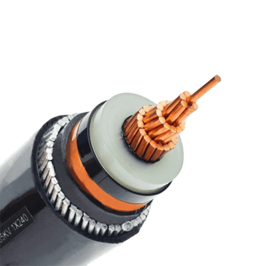
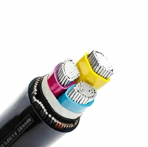
Key Takeaway
Step-by-step 3 phase cable sizing method for motors 1.5kW to 500kW. Covers IEC 60364 derating, voltage drop limits, short-circuit capacity, and worked examples. Free sizing formula + quick-reference tables for copper and aluminium conductors.
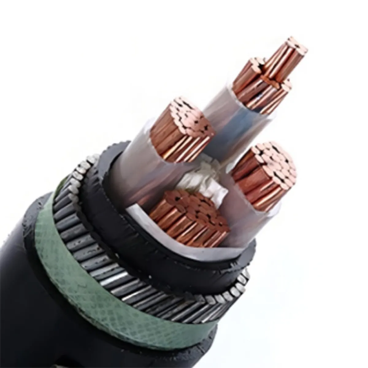
Choosing the wrong cable size for a 3 phase motor is not a minor mistake — it is an installation that will either overheat under load or waste money on oversized copper you did not need. Both outcomes cost you. The first costs downtime and potentially a fire. The second costs thousands of dollars per kilometre in unnecessary conductor material.
This guide walks you through the complete cable sizing process for three-phase motor feeders: from calculating full-load current, through derating for real installation conditions, to checking voltage drop over your actual run length. Every step uses IEC 60364 (the international installation standard) and IEC 60502 (cable construction standard), with cross-references to BS 7671 and NEC where they differ.
If you already know your required cross-section and want to check specifications and current ratings, see our complete 3 phase cable size chart.
Why Cable Sizing Matters More Than You Think
A cable that is technically "rated" for a motor's current can still fail in the field. Here is why:
Published current ratings assume ideal conditions. IEC 60502-1 Table B.3 rates a 3×25mm² Cu/XLPE/SWA cable at 110A — but that assumes 30°C ambient, cables laid directly in ground at 0.8m depth, with thermal resistivity of 1.0 K·m/W. Change any one of those conditions and the actual safe capacity drops.
Motor starting current is 6–8× full-load current. A 30kW motor draws about 57A at full load but pulls 340–460A for 5–15 seconds during direct-on-line starting. Your cable must handle this thermal pulse without exceeding its short-time temperature limit (250°C for XLPE).
Voltage drop kills motor performance before it kills the cable. A motor running at 95% of nominal voltage produces roughly 90% of rated torque (torque scales with V²). If your cable drops 5% on a long run, the motor may not start loaded equipment at all — and you will not see this in a no-load commissioning test.
The cost of getting it right is low. Cable sizing adds 30 minutes of calculation time. The cost of getting it wrong is a re-pull, a cable tray full of scrap, and a project delay measured in weeks.
Step 1: Calculate Motor Full-Load Current (FLC)
The starting point for any cable sizing exercise is the motor full-load current. For a three-phase motor:
Formula:
I_FL = P / (√3 × V_L × η × cosφ)
Where:
- I_FL = Full-load current (Amps)
- P = Motor rated power (Watts)
- V_L = Line-to-line voltage (typically 380V, 400V, or 415V)
- η = Motor efficiency (typically 0.88–0.95 for IE2/IE3 motors)
- cosφ = Power factor at full load (typically 0.82–0.90)
Worked Example: 30kW Motor at 400V
Using conservative estimates for a 30kW IE3 motor: η = 0.91, cosφ = 0.85 (lower bound of nameplate range)
I_FL = 30,000 / (√3 × 400 × 0.91 × 0.85)
I_FL = 30,000 / (1.732 × 400 × 0.91 × 0.85)
I_FL = 30,000 / 535.9
I_FL = 56.0A
Note: The table below uses manufacturer nameplate values, which may differ slightly from these conservative estimates. For cable sizing, always use the higher value (nameplate or calculated) to maintain safety margin.
Quick-Reference: Motor FLC by Power Rating
These are typical nameplate full-load currents for 400V, IE3 efficiency class motors (IEC 60034-30-1). Values represent practical nameplate readings and include manufacturing tolerances — they may be 5–8% higher than pure formula calculation using rated efficiency and power factor:
| Motor Power (kW) | Approx. FLC (A) | Typical Efficiency | Typical PF |
|---|---|---|---|
| 1.5 | 3.4 | 0.84 | 0.79 |
| 2.2 | 4.9 | 0.85 | 0.81 |
| 4 | 8.5 | 0.87 | 0.83 |
| 7.5 | 15.3 | 0.89 | 0.84 |
| 11 | 22.0 | 0.90 | 0.85 |
| 15 | 29.5 | 0.91 | 0.86 |
| 22 | 42.5 | 0.92 | 0.86 |
| 30 | 56.0 | 0.93 | 0.87 |
| 37 | 68.5 | 0.93 | 0.87 |
| 45 | 83.0 | 0.94 | 0.87 |
| 55 | 101 | 0.94 | 0.88 |
| 75 | 137 | 0.95 | 0.88 |
| 90 | 163 | 0.95 | 0.89 |
| 110 | 199 | 0.95 | 0.89 |
| 132 | 238 | 0.96 | 0.89 |
| 160 | 287 | 0.96 | 0.90 |
| 200 | 358 | 0.96 | 0.90 |
| 250 | 447 | 0.97 | 0.90 |
| 315 | 561 | 0.97 | 0.91 |
| 400 | 710 | 0.97 | 0.91 |
| 500 | 886 | 0.97 | 0.91 |
Important: Always verify FLC from the actual motor nameplate. Catalogue values are nominal — the installed motor may differ by ±5%.
Step 2: Apply Design Current Multiplier
You do not size the cable for exactly the motor FLC. Standard practice (IEC 60364-4-43, BS 7671 Regulation 433.1) requires the cable to carry a design current (I_b) that accounts for:
- Motor service factor: Most motors can run continuously at 1.0× rated power, but you should design for at least 1.0× FLC. If the motor may run overloaded (e.g., crushers, conveyors with variable material density), use 1.15–1.25× FLC.
- Future load growth: For main feeders, some engineers apply a 10–20% margin. For dedicated motor circuits, this is usually not needed.
- Harmonic currents: VFD-fed motors produce harmonic currents that increase cable heating. For cables feeding VFDs without output filters, add 5–10% to the calculated FLC.
Rule of thumb for motor feeders:
I_b = 1.0 × I_FL   (for standard duty, DOL or star-delta start)
I_b = 1.25 × I_FL  (for heavy duty, VFD, or cyclic loading)
For our 30kW example: I_b = 56.0A (standard duty)
Step 3: Determine Installation Method and Derating Factors
This is where most cable sizing mistakes happen. The cable's published current rating (from IEC 60502 or manufacturer datasheets) assumes a reference installation condition. Your actual installation almost never matches those assumptions.
IEC 60364-5-52 Installation Methods
The installation method determines the base current rating table you use:
| Reference Method | Description | Typical Application |
|---|---|---|
| A1 | Single-core in conduit in thermally insulated wall | Rarely used for 3-phase motor feeders |
| B1 | Multi-core in conduit on wall | Indoor motor feeders in conduit |
| B2 | Multi-core in conduit in wall | Embedded conduit runs |
| C | Multi-core direct on wall/ceiling | Cable tray, open cleat, cable ladder |
| D1 | Multi-core in buried duct | Underground feeder in HDPE duct |
| D2 | Multi-core direct buried | Direct burial (with armoured cable) |
| E | Multi-core in free air | Vertical risers, open bracket |
| F | Single-core flat touching in free air | Larger motors, parallel runs |
For motor feeders, the most common methods are:
- C (cable tray/ladder) — factories, substations, commercial plant rooms
- D1 (buried in duct) — yard crossings, outdoor motor CCTs to pump houses
- D2 (direct buried) — long runs to remote motors (irrigation pumps, compressor stations)
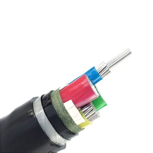
Derating Factors (Correction Factors)
After selecting the installation method, apply derating factors for actual conditions:
1. Ambient Temperature Correction (C_a)
Reference temperature is 30°C for cables in air, 20°C for buried cables.
| Ambient Temp (°C) | XLPE in Air (ref 30°C) | PVC in Air (ref 30°C) | Buried (ref 20°C) XLPE |
|---|---|---|---|
| 20 | 1.08 | 1.12 | — |
| 25 | 1.04 | 1.06 | 1.04 |
| 30 | 1.00 | 1.00 | 0.96 |
| 35 | 0.96 | 0.94 | 0.89 |
| 40 | 0.91 | 0.87 | 0.82 |
| 45 | 0.87 | 0.79 | 0.75 |
| 50 | 0.82 | 0.71 | 0.67 |
| 55 | 0.76 | 0.61 | 0.57 |
| 60 | 0.71 | 0.50 | — |
Values per IEC 60364-5-52 Table B.52.14 / B.52.15
2. Grouping Correction (C_g)
When multiple cables are installed together, they heat each other:
| Number of Circuits | Touching on Tray | Spaced (1× diameter) | Buried in Same Trench |
|---|---|---|---|
| 1 | 1.00 | 1.00 | 1.00 |
| 2 | 0.80 | 0.88 | 0.75 |
| 3 | 0.70 | 0.82 | 0.65 |
| 4 | 0.65 | 0.77 | 0.60 |
| 6 | 0.57 | 0.72 | 0.55 |
| 9 | 0.50 | 0.66 | 0.50 |
Values per IEC 60364-5-52 Table B.52.17
3. Soil Thermal Resistivity (for buried cables)
Reference is 1.0 K·m/W. Actual values vary significantly:
| Soil Type | Thermal Resistivity (K·m/W) | Correction Factor |
|---|---|---|
| Very wet soil (river bank) | 0.5 | 1.28 |
| Damp soil (clay, loam) | 0.7 | 1.13 |
| Normal soil (reference) | 1.0 | 1.00 |
| Dry soil | 1.5 | 0.85 |
| Very dry sand | 2.0 | 0.76 |
| Backfill (cement-bound sand) | 0.5 | 1.28 |
Values per IEC 60287-3-1
Calculating Required Cable Rating
The cable's tabulated current rating (I_z) must satisfy:
I_z ≥ I_b / (C_a × C_g × C_s)
Where:
- I_b = Design current (from Step 2)
- C_a = Ambient temperature correction
- C_g = Grouping correction
- C_s = Soil thermal resistivity correction (only for buried cables)
Worked Example Continued: 30kW Motor
Installation: cable tray in factory (Method C), 40°C ambient (tropical plant), 3 cables touching on tray.
C_a = 0.91 (40°C, XLPE)
C_g = 0.70 (3 circuits touching)
C_s = 1.00 (not buried)

Required I_z ≥ 56.0 / (0.91 × 0.70 × 1.00)
Required I_z ≥ 56.0 / 0.637
Required I_z ≥ 87.9A
So you need a cable with a tabulated rating of at least 88A under reference conditions (Method C, 30°C, single circuit).
Step 4: Select Cable Size from Current Rating Tables
Now match the required current rating to a specific conductor cross-section. Here are the IEC 60502-1 current ratings for 3-core Cu/XLPE/SWA cables (0.6/1kV) under standard conditions:
Method C — On Cable Tray (3-core, copper, XLPE, 30°C air)
| Cross-Section (mm²) | Current Rating (A) | Suitable for Motor up to (kW)* |
|---|---|---|
| 1.5 | 23 | — |
| 2.5 | 31 | 2.2 |
| 4 | 42 | 4 |
| 6 | 53 | 5.5 |
| 10 | 73 | 7.5 |
| 16 | 94 | 15 |
| 25 | 124 | 22 |
| 35 | 154 | 30 |
| 50 | 187 | 37 |
| 70 | 238 | 55 |
| 95 | 289 | 75 |
| 120 | 335 | 90 |
| 150 | 386 | 110 |
| 185 | 441 | 132 |
| 240 | 520 | 160 |
| 300 | 599 | 200 |
| 400 | 673 | 250 |
*Approximate motor size assumes ideal conditions (30°C, single circuit, no derating). Always verify with actual derating calculations.
Method D2 — Direct Buried (3-core, copper, XLPE/SWA, 20°C ground)
| Cross-Section (mm²) | Current Rating (A) | Suitable for Motor up to (kW)* |
|---|---|---|
| 1.5 | 27 | — |
| 2.5 | 36 | 2.2 |
| 4 | 47 | 4 |
| 6 | 59 | 7.5 |
| 10 | 79 | 11 |
| 16 | 102 | 15 |
| 25 | 131 | 22 |
| 35 | 158 | 30 |
| 50 | 188 | 37 |
| 70 | 232 | 55 |
| 95 | 277 | 75 |
| 120 | 316 | 90 |
| 150 | 356 | 110 |
| 185 | 399 | 132 |
| 240 | 461 | 160 |
| 300 | 520 | 200 |
Aluminium Conductors
For aluminium conductor cables, multiply the copper current rating by approximately 0.78 to get the equivalent aluminium rating, or use one size larger:
| Copper Size (mm²) | Equivalent Aluminium Size (mm²) |
|---|---|
| 16 | 25 |
| 25 | 35 |
| 35 | 50 |
| 50 | 70 |
| 70 | 95 |
| 95 | 120 |
| 120 | 150 |
| 150 | 185 |
| 185 | 240 |
| 240 | 300 |
Our 30kW Example: Cable Selection
Required current rating: ≥88A (after derating for 40°C + 3 cables grouped)
From Method C table:
- 16mm² = 94A ✓ (just meets requirement)
- 25mm² = 124A ✓ (comfortable margin)
Select 16mm² or 25mm²? At this stage, 16mm² technically passes on current capacity. But we have not checked voltage drop yet — and that often pushes the selection up one size. Continue to Step 5 before finalising.
Step 5: Check Voltage Drop
Voltage drop is the hidden cable sizing killer. A cable that passes on current capacity can still be too small if the run is long. IEC 60364-5-52 recommends maximum voltage drop of:
- 3% for lighting circuits
- 5% for other circuits (including motors)
For a 400V system, 5% = 20V maximum drop from the distribution board to the motor terminals.
Voltage Drop Formula (3-Phase)
ΔV = √3 × I_b × L × (R·cosφ + X·sinφ) / 1000
Where:
- ΔV = Voltage drop (Volts)
- I_b = Design current (A)
- L = Cable length, one way (meters)
- R = Conductor resistance at operating temperature (mΩ/m)
- X = Conductor reactance (mΩ/m) — typically 0.08 mΩ/m for sizes ≤120mm²
- cosφ = Load power factor
- sinφ = √(1 - cos²φ)
Conductor Resistance Values (at 70°C operating temperature, copper)
| Size (mm²) | DC Resistance at 20°C (Ω/km) | AC Resistance at 70°C (mΩ/m) |
|---|---|---|
| 1.5 | 12.10 | 15.10 |
| 2.5 | 7.41 | 9.24 |
| 4 | 4.61 | 5.75 |
| 6 | 3.08 | 3.84 |
| 10 | 1.83 | 2.28 |
| 16 | 1.15 | 1.43 |
| 25 | 0.727 | 0.907 |
| 35 | 0.524 | 0.654 |
| 50 | 0.387 | 0.483 |
| 70 | 0.268 | 0.334 |
| 95 | 0.193 | 0.241 |
| 120 | 0.153 | 0.191 |
| 150 | 0.124 | 0.155 |
| 185 | 0.0991 | 0.124 |
| 240 | 0.0754 | 0.094 |
| 300 | 0.0601 | 0.075 |
DC resistance from IEC 60228 Table 2. AC resistance at 70°C = R_20 × [1 + 0.00393 × (70-20)] × skin effect factor
Worked Example: 30kW Motor, 80m Cable Run
Using 16mm² cable:
I_b = 56A
L = 80m
R = 1.43 mΩ/m (16mm² Cu at 70°C)
X = 0.08 mΩ/m
cosφ = 0.87, sinφ = 0.493

ΔV = √3 × 56 × 80 × (1.43×0.87 + 0.08×0.493) / 1000
ΔV = 1.732 × 56 × 80 × (1.244 + 0.039) / 1000
ΔV = 7,759 × 1.283 / 1000
ΔV = 9.95V
Percentage drop: 9.95 / 400 × 100 = 2.5% ✓ (within 5% limit)
So for an 80m run, 16mm² passes on voltage drop too.
But what if the run is 200m?
ΔV = 1.732 × 56 × 200 × 1.283 / 1000
ΔV = 24.9V → 6.2% ✗ FAILS
At 200m, you must go up to 25mm²:
ΔV = 1.732 × 56 × 200 × (0.907×0.87 + 0.08×0.493) / 1000
ΔV = 1.732 × 56 × 200 × (0.789 + 0.039) / 1000
ΔV = 19,398 × 0.828 / 1000
ΔV = 16.1V → 4.0% ✓
Quick Voltage Drop Reference (Copper, 3-Phase, PF=0.85)
Maximum cable length (meters) for 5% drop at full-load current:
| Size (mm²) | 30kW/56A | 45kW/83A | 55kW/101A | 75kW/137A | 110kW/199A |
|---|---|---|---|---|---|
| 10 | 104 | 70 | 58 | 43 | 29 |
| 16 | 164 | 111 | 91 | 67 | 46 |
| 25 | 254 | 171 | 141 | 104 | 71 |
| 35 | 345 | 233 | 191 | 141 | 97 |
| 50 | 455 | 307 | 253 | 186 | 128 |
| 70 | 632 | 427 | 351 | 259 | 178 |
| 95 | 835 | 563 | 463 | 341 | 235 |
| 120 | 1008 | 680 | 559 | 412 | 284 |
| 150 | 1186 | 800 | 657 | 485 | 334 |
Reading the table: For a 30kW motor (56A) on a 25mm² cable, the maximum one-way distance for 5% voltage drop is 254m. Beyond that, go up to 35mm².
Step 6: Verify Short-Circuit Withstand
The final check: can the cable survive a fault without melting? This matters because:
- A motor feeder is protected by a circuit breaker or fuse
- The breaker takes time to trip (typically 0.1–0.4 seconds for short-circuit)
- During that time, enormous fault current flows through the cable
Adiabatic Equation (IEC 60364-5-54)
S ≥ √(I²t) / k
Where:
- S = Minimum conductor cross-section (mm²)
- I = Prospective short-circuit current at the cable (A)
- t = Disconnection time (seconds)
- k = Conductor material constant (143 for copper/XLPE, 76 for aluminium/XLPE)
Example: 30kW Motor Circuit
Assume:
- Prospective fault current at distribution board: 15kA
- Breaker trips in 0.1 seconds (instantaneous magnetic release)
S ≥ √(15000² × 0.1) / 143
S ≥ √(22,500,000) / 143
S ≥ 4,743 / 143
S ≥ 33.2mm²
Wait — this suggests we need 35mm² minimum for short-circuit protection, even though current capacity only required 16mm².
This is why you must always check short-circuit. In practice, if the fault level is this high and breaker clearing time is 0.1s, the short-circuit check may govern cable size rather than current capacity.
However — review whether 0.1s is realistic. Modern MCCBs with electronic trip units can clear in 0.02–0.05s for instantaneous trips:
At 0.05s: S ≥ √(15000² × 0.05) / 143 = 3,354 / 143 = 23.5mm² → 25mm² OK
At 0.02s: S ≥ √(15000² × 0.02) / 143 = 2,121 / 143 = 14.8mm² → 16mm² OK
Key takeaway: Always confirm the actual fault level at the point of connection and the proven disconnection time of your protective device. Do not assume — get the protection coordination study from your electrical consultant. If you would rather have the short-circuit size checked against your fault level, send us the figures.
Step 7: Final Cable Selection — Putting It All Together
Let us complete our 30kW motor example and show the full decision process:
Given:
- Motor: 30kW, 400V, 3-phase, IE3, DOL start
- Installation: Cable tray in factory, 40°C ambient, 3 circuits grouped
- Run length: 80m one way
- Fault level: 15kA, MCCB clearing time 0.05s
Calculations:
| Step | Check | Requirement | Result |
|---|---|---|---|
| 1 | Full-load current | I_FL = 56A | — |
| 2 | Design current | I_b = 56A (1.0× for standard duty) | — |
| 3 | Derating | C_a=0.91, C_g=0.70 → required I_z ≥ 88A | 16mm² (94A) passes |
| 4 | Current rating | Select from table | 16mm² OK |
| 5 | Voltage drop | 80m run → 2.5% | 16mm² OK |
| 6 | Short-circuit | 15kA × 0.05s → need ≥ 25mm² | 16mm² FAILS |
Final selection: 25mm² Cu/XLPE/SWA 3-core cable
The short-circuit check pushed us up from 16mm² to 25mm². This is common in industrial installations with high fault levels. The 25mm² cable provides:
- Current capacity: 124A (41% margin over 88A required)
- Voltage drop at 80m: 1.6% (well within 5%)
- Short-circuit withstand: 25mm² > 23.5mm² required ✓
Complete Motor-to-Cable Selection Chart
Here is a consolidated quick-reference for the most common scenario: Cu/XLPE/SWA cable on tray, 35°C ambient, 2 circuits grouped, 100m run, moderate fault level (10kA, 0.1s clear):
| Motor (kW) | FLC (A) | Derated Requirement (A) | Selected Size (mm²) | VD at 100m | Passes All? |
|---|---|---|---|---|---|
| 1.5 | 3.4 | 4.4 | 1.5 | 1.9% | ✓ |
| 2.2 | 4.9 | 6.4 | 1.5 | 2.8% | ✓ |
| 4 | 8.5 | 11.1 | 2.5 | 3.0% | ✓ |
| 7.5 | 15.3 | 19.9 | 4 | 3.3% | ✓ |
| 11 | 22.0 | 28.6 | 6 | 3.2% | ✓ |
| 15 | 29.5 | 38.4 | 10 | 2.6% | ✓ |
| 22 | 42.5 | 55.3 | 16 | 2.4% | ✓ |
| 30 | 56.0 | 72.9 | 16 | 3.1% | ✓* |
| 37 | 68.5 | 89.2 | 25 | 2.5% | ✓ |
| 45 | 83.0 | 108 | 25 | 3.0% | ✓ |
| 55 | 101 | 131 | 35 | 2.7% | ✓ |
| 75 | 137 | 178 | 50 | 2.7% | ✓ |
| 90 | 163 | 212 | 70 | 2.3% | ✓ |
| 110 | 199 | 259 | 70 | 2.8% | ✓ |
| 132 | 238 | 310 | 95 | 2.6% | ✓ |
| 160 | 287 | 373 | 120 | 2.6% | ✓ |
| 200 | 358 | 466 | 150 | 2.7% | ✓ |
| 250 | 447 | 582 | 185 | 2.9% | ✓ |
| 315 | 561 | 730 | 240 | 2.9% | ✓ |
| 400 | 710 | 924 | 300 | 3.2% | ✓ |
| 500 | 886 | 1153 | 2×240 | 2.3% | ✓ |
*Check short-circuit separately — it may require a larger size at high fault levels.
For detailed specifications, current ratings across all configurations, and pricing for these cable sizes, see our complete 3 phase cable specification guide.
Common Mistakes in 3 Phase Cable Sizing
After reviewing hundreds of cable schedules from projects across Africa, the Middle East, and Southeast Asia, these are the errors we see most often:
Mistake #1: Using Nameplate Current Without Checking
Many engineers take the motor nameplate current and go straight to the cable table without applying derating factors. In a 45°C ambient with grouped cables, this underestimates the required cable size by 35–40%.
Fix: Always calculate the derated requirement. A 56A motor in harsh conditions needs a cable rated for 88A+ at reference conditions.
Mistake #2: Ignoring Voltage Drop on Long Runs
This is especially common in:
- Mining sites (motor 500m+ from switchgear)
- Irrigation pump stations (pump house 200–300m from transformer)
- Construction sites with temporary cabling
A cable that is perfectly sized for current capacity at 30m becomes completely inadequate at 200m.
Fix: Always calculate voltage drop for runs over 50m. Use the quick-reference table above or the formula.
Mistake #3: Selecting Aluminium Without Adjusting Size
Aluminium is 60% cheaper per meter than copper for the same cross-section — but it only carries 78% of the current. Engineers sometimes specify "95mm² aluminium" as a direct replacement for "95mm² copper" without realising they have reduced the circuit capacity by 22%.
Fix: Use the copper-to-aluminium equivalence table. 95mm² copper = 120mm² aluminium.
Mistake #4: Not Accounting for Motor Starting
For DOL (direct-on-line) starting, the motor draws 6–8× FLC for 5–15 seconds. The cable must tolerate this thermally. For most XLPE cables sized correctly for continuous current, this is not a problem — the thermal time constant of the cable is much longer than the starting time. But for:
- Very long starting times (>20 seconds, e.g., high-inertia loads)
- Repeated starts (compressors with frequent cycling)
- Star-delta transition (momentary interruption causes double transient)
...you should verify the cable's short-time thermal limit is not exceeded.
Mistake #5: Choosing PVC When XLPE Is Needed
PVC-insulated cable has a maximum operating temperature of 70°C. XLPE operates at 90°C continuously. This means:
- PVC carries about 15–20% less current than XLPE for the same conductor size
- PVC cables in hot environments (>35°C) derate much faster
- PVC short-circuit temperature limit is 160°C vs 250°C for XLPE
For any motor feeder above 15kW in a tropical or industrial plant environment, XLPE insulation is the standard choice. PVC is adequate only for small motors in temperature-controlled environments.
For a detailed comparison of insulation materials and when each is appropriate, read our guide on cable insulation types.
Regional Standard Differences: IEC vs BS vs NEC
Cable sizing methodology is broadly the same worldwide, but reference tables and specific rules differ by region. Here is what you need to know if you are sourcing cable for different markets:
IEC 60364 (International — Africa, Middle East, Asia, South America)
- Installation methods: A1, A2, B1, B2, C, D1, D2, E, F, G
- Ambient reference: 30°C air, 20°C ground
- Voltage drop recommendation: 3% lighting, 5% power (advisory, not mandatory in IEC)
- Short-circuit check: Adiabatic equation mandatory
- Standard cable: IEC 60502-1 (0.6/1kV), IEC 60502-2 (6/10kV – 18/30kV)
BS 7671 (UK, Nigeria, Kenya, most Commonwealth countries)
- Same IEC installation methods (BS 7671 18th Edition adopted IEC numbering)
- Voltage drop limit: 3% lighting, 5% power — mandatory (Regulation 525.1)
- Additional: Appendix 4 provides precalculated mV/A/m values for direct table lookup
- Standard cable: BS 5467 (armoured, 0.6/1kV), BS 6724 (LSZH)
NEC / NFPA 70 (USA, some Caribbean/Central American countries)
- Different installation method classification (raceway types, open wiring, etc.)
- Conductor sizes in AWG/kcmil (not mm²): #14 AWG ≈ 2.08mm², #1/0 ≈ 53.5mm², 500kcmil ≈ 253mm²
- Voltage drop: NEC 210.19 and 215.2 Informational Notes recommend 3%/5% but not mandatory code
- Ambient reference: 30°C
- Article 310 provides ampacity tables; Article 430 covers motor circuits specifically
- Motor circuit conductor sizing: NEC 430.22 requires 125% of motor FLC for continuous duty
- Standard cable: UL listed per NEC 334/338 (NM-B, SE cable) — structurally different from IEC cables
What This Means for International Procurement
If you are buying cable from a Chinese factory for a project in Nigeria (BS standard), you need cable manufactured to BS 5467 (not just IEC 60502-1). The cable dimensions, test voltages, and marking requirements differ slightly.
We manufacture to IEC 60502, BS 5467, and NF C 33-210 from the same production lines — the difference is in final testing parameters and cable marking. When you request a quote, specify which standard your project requires, and we will provide the matching test certificate. Projects in Nigeria and other BS-standard markets need the BS documentation set, not the IEC one.
For a complete overview of how international standards map to specific cable constructions, see our IEC and KEMA certification guide.
Special Cases: VFDs, Long Runs, and Parallel Cables
Variable Frequency Drive (VFD) Fed Motors
When a motor is fed through a VFD (variable frequency drive / inverter), additional cable sizing considerations apply:
Output cable (VFD to motor):
- VFD output waveform contains high-frequency harmonics that increase cable heating by 5–15%
- dV/dt from PWM switching causes additional dielectric stress on insulation
- Recommended: use cable with symmetrical construction (3-core preferred over single-core trefoil) to balance capacitive charging currents
- Screen/armour must be earthed at both ends to contain EMI
- Maximum length is limited by VFD — typically 50–100m unshielded, up to 300m with output reactor
Input cable (supply to VFD):
- VFD input current contains 5th and 7th harmonics (THDi typically 30–40% for 6-pulse drives)
- Derate cable by additional 10–15% for harmonic heating
- If neutral conductor is present, it carries triplen harmonics — size neutral at 100% of phase conductor (not reduced)
Parallel Cable Runs (>300mm² requirement)
For motors above 400kW (or for very long runs where a single cable cannot meet voltage drop), you need parallel cables:
Rules for parallel operation:
- All parallel cables must be identical (same size, same length, same route, same termination method)
- Length difference must be less than 5% between parallels
- Each cable carries I_total / N (where N = number of parallels)
- Each cable must be individually protected or the protection must be rated for the combined I²t
- Preferred arrangement: each parallel set carries all 3 phases (3-core cables) rather than single-phase parallels
Example: 500kW motor at 400V
- FLC ≈ 886A
- After derating (35°C, 2 groups): required I_z per parallel ≈ 580A
- Single cable option: 2× 240mm² Cu/XLPE/SWA per phase (complex, expensive terminations)
- Better option: 2 runs of 3×240mm² Cu/XLPE/SWA cable (each carries 443A, rated 504A) ✓
Very Long Runs (>500m)
For remote installations (irrigation pumps, mining conveyors, oilfield artificial lift):
- Voltage drop governs — you may need cable 3–4 sizes larger than the current rating requires
- Consider increasing system voltage — a pump at 1km is better served by 3.3kV or 6.6kV supply than trying to push 400V over that distance
- Aluminium becomes more attractive — the cost saving of Al over Cu is magnified at large sizes, and the one-size-up penalty matters less when voltage drop already forced a large cable
- Series voltage regulation — for fixed loads, some engineers add a booster transformer at the motor end rather than oversizing the entire cable run
For underground installation methods for long cable runs, see our burial depth and duct derating rules.
Cable Sizing Checklist (Copy This for Your Next Project)
Use this systematic checklist for every motor feeder cable you size:
☐ Step 1 — Motor Data
- Motor kW rating confirmed from nameplate/datasheet
- Supply voltage confirmed (380V / 400V / 415V / 440V)
- Motor efficiency and power factor noted (or use table estimates)
- Full-load current calculated: I_FL = ___A
- Starting method confirmed (DOL / Star-Delta / Soft Starter / VFD)
☐ Step 2 — Design Current
- Service factor applied (1.0 standard / 1.25 heavy duty)
- Harmonic allowance applied if VFD-fed (+10%)
- Design current I_b = ___A
☐ Step 3 — Installation Conditions
- Installation method identified (C / D1 / D2 / other)
- Ambient temperature measured/specified: ___°C
- Number of grouped circuits counted: ___
- Soil resistivity known (if buried): ___ K·m/W
- All derating factors multiplied: C_total = ___
- Required cable rating: I_z ≥ I_b / C_total = ___A
☐ Step 4 — Cable Selection
- Conductor material: Cu / Al
- Insulation type: XLPE / PVC
- Armour: SWA / STA / Unarmoured
- Selected size: ___mm²
- Tabulated current rating: ___A ≥ required ✓/✗
☐ Step 5 — Voltage Drop
- Cable run length (one way): ___m
- Voltage drop calculated: ___%
- Within limit (5% for motors): ✓/✗
- If fails: go up one size and recalculate
☐ Step 6 — Short-Circuit
- Fault level at cable origin: ___kA
- Protection device clearing time: ___s
- Minimum cable size from adiabatic equation: ___mm²
- Selected size ≥ minimum: ✓/✗
☐ Step 7 — Final Confirmation
- Cable passes all three checks (current / VD / SC)
- Cable specified with full designation (e.g., "3×25mm² Cu/XLPE/SWA/PVC 0.6/1kV")
- Standard specified (IEC 60502-1 / BS 5467 / other)
- Quantity and lengths confirmed for procurement
Frequently Asked Questions
What size cable do I need for a 30kW 3 phase motor?
For a 30kW motor at 400V (approximately 56A full-load current), the minimum cable size depends on your installation conditions. Under standard conditions (cable tray, 30°C ambient, single circuit), 16mm² Cu/XLPE is adequate. However, with tropical ambient temperatures (40°C+), grouped cables, or long runs (>100m), you will typically need 25mm². If fault levels exceed 10kA with slow protection, 35mm² may be required. Always perform the full calculation — do not rely on rules of thumb for critical installations.
How do I calculate cable size for a 3 phase motor?
The process has 6 steps: (1) Calculate motor full-load current using I = P/(√3×V×η×cosφ), (2) Apply design current multiplier for duty type, (3) Apply derating factors for ambient temperature, cable grouping, and soil conditions, (4) Select cable size from current rating tables (IEC 60502 or BS appendix), (5) Verify voltage drop is within 5% for the actual run length, (6) Check short-circuit withstand using the adiabatic equation. The cable must pass ALL three checks — current capacity, voltage drop, and short-circuit — simultaneously.
Can I use aluminium cable for motor feeders?
Yes — aluminium conductor cables are widely used for motor feeders, especially for larger motors (>37kW) where the cost saving is significant. The key is to use one size larger than the equivalent copper cable. For example, where copper requires 95mm², specify 120mm² aluminium. Aluminium is particularly cost-effective for long buried runs to remote motors (pumps, compressors) where the cable cost dominates the project budget. Ensure your terminations (lugs, glands) are rated for aluminium — do not use copper-only connectors.
What is the maximum cable length for a motor feeder?
There is no fixed maximum — it depends on cable size, motor current, and acceptable voltage drop. As a practical guide for 400V systems: with 25mm² copper cable, you can run a 30kW motor up to about 250m before hitting 5% voltage drop. With 50mm² copper, that extends to approximately 455m. Beyond 300–500m for most motor sizes, you should consider: (a) increasing cable size specifically for voltage drop, (b) using medium voltage (3.3kV or 6.6kV) distribution, or (c) adding a local transformer near the motor.
Does motor starting current affect cable sizing?
For most correctly-sized cables with standard DOL starting (duration 5–15 seconds), starting current does not require a larger cable — the thermal time constant of the cable insulation is much longer than the starting pulse. However, you should verify if: (a) starting time exceeds 20 seconds, (b) the motor starts frequently (more than 6 times per hour), or (c) you are using star-delta starting where the transition transient adds stress. In these cases, perform a thermal calculation per IEC 60364-4-43 Annex A.
IEC standard or BS standard — which should I follow?
Both give the same fundamental methodology and nearly identical results. IEC 60364 is the base international standard; BS 7671 is the UK national implementation with some additional rules (mandatory voltage drop limits, specific cable types like BS 5467). For projects in Africa and the Middle East, specify IEC 60502-1 cable tested to BS 5467 where required by the local authority — this gives you internationally-recognized cable with UK-standard test compliance. Chinese manufacturers produce to both standards from the same production lines.
Related Guides & Sourcing
Dig deeper into sizing:
- Cable Size Chart: mm² to AWG, Amps by Size
- PVC, XLPE and EPR insulation compared — pick the right insulation for the run
Pricing & sourcing your motor cable:
- What drives XLPE cable cost per metre
- SWA Cable Price Per Meter: Factory Cost Guide
- Factory sourcing checklist for XLPE cable — how to choose a factory
- From RFQ to delivered container
Ready to Order 3 Phase Motor Cable?
Once you have determined your cable size using the steps above, we can supply the exact specification you need — manufactured to IEC 60502-1, BS 5467, or NF C 33-210 depending on your project standard. Our full power cable range is produced to order.
What to include in your enquiry:
- Cable designation (e.g., 3×25mm² Cu/XLPE/SWA/PVC 0.6/1kV)
- Applicable standard (IEC / BS / NF)
- Total length required (meters or km)
- Delivery destination (for shipping cost estimation)
- Any special requirements (fire rating, LSZH sheath, specific colour coding)
We supply MOQ from 1 km per size for standard constructions. Factory lead time is typically 15–25 days depending on conductor size and current order volume.