Key Takeaway
Complete SWA cable sizing guide with current ratings, voltage drop tables, correction factors, and selection tips for EPC contractors and bulk buyers.
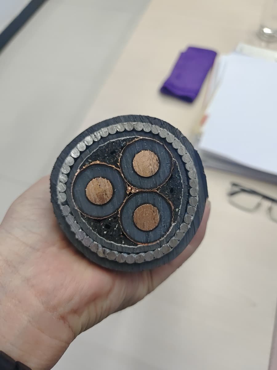
Choosing the wrong SWA cable size costs money — either through oversizing (wasted material on thousands of meters) or undersizing (overheating, voltage drop issues, failed inspections, and potential rework). For EPC contractors and project buyers ordering hundreds or thousands of meters, getting the size right before placing the order is not optional.
This guide covers everything you need to size SWA cables correctly: current-carrying capacity tables, voltage drop calculations, correction factors for real-world installation conditions, and a step-by-step selection process that works for any project scale. If you are also evaluating cost, see our SWA cable price per meter breakdown for size-by-size factory pricing.
The 4 Factors That Determine SWA Cable Size
Cable sizing is not a single calculation. Four parameters must all be satisfied simultaneously — the cable you select must pass every check, not just one.
1. Current-Carrying Capacity (Ampacity)
The cable must carry the full load current without exceeding its rated operating temperature (70°C for PVC-insulated, 90°C for XLPE-insulated SWA cables). If the conductor overheats, insulation degrades, lifespan shortens, and fire risk increases.
2. Voltage Drop
Over long cable runs, resistance causes voltage to drop between the supply and the load. Most standards limit voltage drop to 3–5% of nominal voltage. A cable that passes the ampacity check may still fail on voltage drop if the run is long — requiring a larger conductor to compensate.
3. Short-Circuit Withstand
The cable must survive the maximum fault current for the duration it takes the protection device to trip. This is especially critical on high-fault-level networks fed by large transformers. Undersized cables can melt or catch fire during a short circuit.
4. Earth Fault Loop Impedance
The cable's earth path (usually the steel wire armour itself for SWA cables) must have low enough impedance to allow sufficient fault current to flow and trip the protective device within the required disconnection time.
For bulk procurement purposes, factors 1 and 2 (ampacity and voltage drop) drive the size selection in 90%+ of cases. Factors 3 and 4 are verified by the project electrical engineer during detailed design but rarely change the conductor size chosen based on ampacity and voltage drop.
SWA Cable Current Rating Tables (per IEC 60502-1 & BS 7671)
The following tables provide current-carrying capacities for XLPE-insulated SWA cables based on IEC 60502-1 Table B.5 and BS 7671 Table 4D4A/4D4B reference methods. These are base ratings at 30°C ambient temperature, laid in free air or directly buried. For a full breakdown of how these standards differ in testing and marking requirements, see our SWA cable standards comparison.
2-Core SWA Cable — Current Ratings (Amps)
| Conductor Size (mm²) | Clipped to Surface (Method C) | Direct Buried (Method D) | In Trefoil on Tray (Method E) |
|---|---|---|---|
| 1.5 | 25 | 27 | 23 |
| 2.5 | 34 | 36 | 31 |
| 4 | 45 | 47 | 41 |
| 6 | 57 | 59 | 52 |
| 10 | 78 | 80 | 71 |
| 16 | 104 | 105 | 94 |
| 25 | 137 | 135 | 119 |
| 35 | 167 | 163 | 146 |
| 50 | 202 | 196 | 175 |
| 70 | 253 | 243 | 218 |
| 95 | 306 | 290 | 261 |
| 120 | 352 | 330 | 298 |
| 150 | 399 | 372 | 339 |
| 185 | 456 | 420 | 382 |
| 240 | 536 | 488 | 447 |
| 300 | 611 | 552 | 507 |
3-Core SWA Cable — Current Ratings (Amps)
| Conductor Size (mm²) | Clipped to Surface (Method C) | Direct Buried (Method D) | In Trefoil on Tray (Method E) |
|---|---|---|---|
| 1.5 | 22 | 24 | 20 |
| 2.5 | 30 | 32 | 27 |
| 4 | 40 | 42 | 36 |
| 6 | 51 | 53 | 46 |
| 10 | 69 | 71 | 63 |
| 16 | 91 | 93 | 83 |
| 25 | 119 | 119 | 106 |
| 35 | 146 | 144 | 129 |
| 50 | 175 | 172 | 154 |
| 70 | 221 | 213 | 193 |
| 95 | 266 | 254 | 231 |
| 120 | 305 | 290 | 263 |
| 150 | 349 | 328 | 300 |
| 185 | 397 | 371 | 340 |
| 240 | 466 | 432 | 398 |
| 300 | 532 | 490 | 453 |
4-Core SWA Cable — Current Ratings (Amps)
| Conductor Size (mm²) | Clipped to Surface (Method C) | Direct Buried (Method D) | In Trefoil on Tray (Method E) |
|---|---|---|---|
| 1.5 | 22 | 24 | 20 |
| 2.5 | 30 | 32 | 27 |
| 4 | 40 | 42 | 36 |
| 6 | 51 | 53 | 46 |
| 10 | 69 | 71 | 63 |
| 16 | 91 | 93 | 83 |
| 25 | 119 | 119 | 106 |
| 35 | 146 | 144 | 129 |
| 50 | 175 | 172 | 154 |
| 70 | 221 | 213 | 193 |
| 95 | 266 | 254 | 231 |
| 120 | 305 | 290 | 263 |
| 150 | 349 | 328 | 300 |
| 185 | 397 | 371 | 340 |
| 240 | 466 | 432 | 398 |
| 300 | 532 | 490 | 453 |
Note for procurement: These are base ratings before correction factors are applied. The actual installed rating will be lower once grouping, ambient temperature, and soil thermal resistivity corrections are factored in. Always confirm the derated values with your project engineer before finalizing cable sizes.
Data reference: IEC 60502-1 Table B.5, BS 7671 Tables 4D4A & 4D4B, installation methods per IEC 60364-5-52.
Correction Factors: Why Base Ratings Are Not Enough
Base current ratings assume ideal conditions: single cable, 30°C ambient, standard soil thermal resistivity. Real installations rarely match these assumptions. Correction factors reduce the allowable current to account for actual conditions.
Ambient Temperature Correction Factor (Ca)
When ambient temperature exceeds 30°C (common in tropical regions, the Middle East, and enclosed spaces), the cable's ability to dissipate heat decreases.
| Ambient Temperature (°C) | XLPE Insulation (90°C rated) | PVC Insulation (70°C rated) |
|---|---|---|
| 25 | 1.04 | 1.06 |
| 30 | 1.00 | 1.00 |
| 35 | 0.96 | 0.94 |
| 40 | 0.91 | 0.87 |
| 45 | 0.87 | 0.79 |
| 50 | 0.82 | 0.71 |
| 55 | 0.76 | 0.61 |
| 60 | 0.71 | 0.50 |
Source: BS 7671 Table 4B1, IEC 60364-5-52 Table B.52.14
Practical impact: A project in Saudi Arabia with 50°C ambient temperature using PVC-insulated SWA must derate by 29% (factor 0.71). This can push a 95mm² cable up to 120mm² or even 150mm² — a significant cost difference on large orders. XLPE insulation handles high ambient temperatures far better (see our cable insulation types comparison), which is why most industrial and infrastructure projects specify XLPE.
Grouping Correction Factor (Cg)
When multiple cables are installed together (in trenches, on trays, or in ducts), they heat each other. The more cables grouped together, the lower each cable's allowable current.
| Number of Circuits | Touching (Single Layer) | Spaced (One Diameter Apart) |
|---|---|---|
| 1 | 1.00 | 1.00 |
| 2 | 0.80 | 0.85 |
| 3 | 0.70 | 0.76 |
| 4 | 0.65 | 0.72 |
| 5 | 0.60 | 0.68 |
| 6 | 0.57 | 0.64 |
| 7 | 0.54 | 0.61 |
| 8 | 0.52 | 0.59 |
| 9 | 0.50 | 0.57 |
| 12 | 0.45 | 0.52 |
| 16 | 0.41 | 0.48 |
| 20 | 0.38 | 0.45 |
Source: BS 7671 Table 4C1, IEC 60364-5-52 Table B.52.17
Practical impact: A cable trench with 6 circuits touching requires a 43% derating. This is the single biggest factor that drives cable sizes up on large projects. Specifying proper cable spacing in the trench design can save 1–2 conductor sizes across the entire project — potentially tens of thousands of dollars in material cost.
Soil Thermal Resistivity Correction Factor (Cs) — Buried Cables Only
Direct-buried cables rely on surrounding soil to carry heat away. Dry, sandy soil conducts heat poorly, while moist clay conducts it well.
| Soil Thermal Resistivity (K·m/W) | Correction Factor |
|---|---|
| 0.5 (very wet soil) | 1.28 |
| 0.7 (wet soil) | 1.15 |
| 1.0 (standard — damp soil) | 1.00 |
| 1.5 (dry soil) | 0.86 |
| 2.0 (very dry soil) | 0.76 |
| 2.5 (extremely dry — desert) | 0.70 |
| 3.0 (arid sand) | 0.65 |
Source: IEC 60287-3-1, BS 7671 Table 4C3
Practical impact: Desert installations (common in MENA region projects) with thermal resistivity of 2.5 K·m/W require a 30% derating on top of the ambient temperature correction. Combined, these two factors alone can require cables 2–3 sizes larger than the base rating suggests.
Depth of Burial Correction Factor (Cd)
Standard burial depth is 0.5m for low voltage and 0.8m for medium voltage. Deeper installation means less heat dissipation.
| Burial Depth | Correction Factor |
|---|---|
| 0.5 m | 1.00 |
| 0.8 m | 0.97 |
| 1.0 m | 0.95 |
| 1.25 m | 0.92 |
| 1.5 m | 0.89 |
| 2.0 m | 0.85 |
Applying Multiple Correction Factors
The derated current-carrying capacity is calculated as:
Iz (derated) = It (base table value) × Ca × Cg × Cs × Cd
Example: A 3-core 95mm² XLPE SWA cable, direct buried at 1.0m depth, in 40°C ambient, dry soil (1.5 K·m/W), with 4 other cables touching in the same trench:
- Base rating (Method D): 254A
- Ca (40°C, XLPE): 0.91
- Cg (5 circuits touching): 0.60
- Cs (dry soil): 0.86
- Cd (1.0m): 0.95
Iz = 254 × 0.91 × 0.60 × 0.86 × 0.95 = 113A
The 95mm² cable that carries 254A under ideal conditions can only safely carry 113A in these real-world conditions — a 55% reduction. If the load is 150A, you need to move up to 150mm² or even 185mm² after applying the same corrections.
This is why experienced EPC contractors always specify installation conditions when requesting cable quotes. The installed conditions directly determine the size — and therefore the cost. For a detailed cost breakdown by size, see our SWA cable pricing guide.
Voltage Drop Calculation for SWA Cables
Even when a cable passes the ampacity check, it may fail on voltage drop — especially on long runs common in industrial plants, solar farms, and distribution networks.
Voltage Drop Limits by Standard
| Standard | Max Voltage Drop (from origin to load) |
|---|---|
| BS 7671 (UK) | 3% lighting, 5% other (total from origin) |
| IEC 60364 | 3% lighting, 5% power |
| AS/NZS 3008 (Australia) | 5% total (combined main + sub) |
| NEC (USA) | 3% branch, 5% total (recommended, not mandatory) |
Voltage Drop Formula
Vd = (mV/A/m × Ib × L) / 1000
Where:
- mV/A/m = voltage drop per amp per meter (from cable data tables)
- Ib = design current in amps
- L = cable length in meters
- Result is in volts
SWA Cable Voltage Drop Values (mV/A/m) at 90°C — XLPE Insulated
| Conductor Size (mm²) | 2-Core (1-phase) | 3/4-Core (3-phase) |
|---|---|---|
| 1.5 | 29.0 | 25.0 |
| 2.5 | 18.0 | 15.5 |
| 4 | 11.0 | 9.5 |
| 6 | 7.3 | 6.4 |
| 10 | 4.4 | 3.8 |
| 16 | 2.8 | 2.4 |
| 25 | 1.75 | 1.50 |
| 35 | 1.25 | 1.10 |
| 50 | 0.93 | 0.80 |
| 70 | 0.63 | 0.55 |
| 95 | 0.46 | 0.40 |
| 120 | 0.36 | 0.31 |
| 150 | 0.29 | 0.25 |
| 185 | 0.24 | 0.21 |
| 240 | 0.185 | 0.160 |
| 300 | 0.155 | 0.135 |
Worked Example: Sizing for Voltage Drop
Scenario: 3-phase motor load, 80A, cable run 200m, supply voltage 400V, maximum voltage drop 5%.
Step 1: Maximum allowable drop = 400 × 0.05 = 20V
Step 2: Required mV/A/m = (20 × 1000) / (80 × 200) = 1.25 mV/A/m
Step 3: From the table, 35mm² gives 1.10 mV/A/m (passes). Check: 35mm² 3-core current rating = 146A (Method C) — passes ampacity check too.
Step 4: Actual voltage drop = (1.10 × 80 × 200) / 1000 = 17.6V = 4.4% ✓
But wait — if this cable is installed with 3 other circuits (Cg = 0.65), the derated ampacity of 35mm² becomes 146 × 0.65 = 95A. Still above 80A, so 35mm² works. If the load were higher, you might need to go up to 50mm² purely due to grouping.
When Voltage Drop Drives the Size
On runs over 100m, voltage drop frequently becomes the controlling factor rather than ampacity. Common scenarios:
- Solar farms: Combiner box to inverter runs of 200–500m
- Mining sites: Surface to underground power cable feeds of 300–1000m
- Industrial plants: MCC to remote motor loads of 150–400m
- Distribution networks: Substation to building main switchboards of 200–800m
For these applications, contractors often need cables 1–3 sizes larger than ampacity alone would require. This is critical information when budgeting — a project with average run lengths over 200m will use significantly more copper/aluminium than a compact installation.
Step-by-Step SWA Cable Sizing Process
Here is the systematic process used by electrical engineers and EPC contractors to select SWA cable sizes. Follow this sequence to determine the correct size for your project.
Step 1: Determine Design Current (Ib)
Calculate the maximum continuous current the cable must carry:
- Motor loads: Full load current × 1.0 (motor protection handles starting current)
- General power: Total connected load × diversity factor
- Lighting: Total lamp watts ÷ voltage × power factor
- Distribution submains: Maximum demand of downstream board (from load schedule)
Step 2: Identify Installation Conditions
Document all conditions that affect cable rating:
- Installation method: Buried, clipped, in tray, in duct, in trench
- Ambient/ground temperature: Actual maximum, not average
- Grouping: How many other cables are nearby, and at what spacing
- Soil conditions (if buried): Thermal resistivity, moisture content
- Burial depth: Actual depth to cable centerline
Step 3: Calculate Required Tabulated Rating (It)
It = Ib / (Ca × Cg × Cs × Cd)
This is the minimum base table rating the cable must have. Select from the current rating tables above the smallest size where the table value ≥ It.
Step 4: Check Voltage Drop
Using the mV/A/m table and the actual cable length:
Vd = (mV/A/m × Ib × L) / 1000
If Vd exceeds the allowable limit, increase cable size until it passes.
Step 5: Verify Short-Circuit Withstand (if required)
For cables on high-fault-level networks, verify that:
k²S² ≥ I²t
Where:
- k = conductor material constant (143 for copper/XLPE, 76 for aluminium/XLPE)
- S = conductor cross-section (mm²)
- I = prospective fault current (A)
- t = disconnection time (seconds)
Step 6: Select Final Size
The final cable size is the largest size required by any of the above checks. In most cases, this will be determined by either ampacity (Step 3) or voltage drop (Step 4).
Common Project Scenarios: Quick Size Reference
Rather than running calculations from scratch for every circuit, here are sizing results for common project scenarios that EPC contractors and facility managers encounter regularly.
Scenario 1: Submain to Distribution Board (Commercial Building)
| Load (A) | Run Length (m) | Min Size (Ampacity) | Min Size (Voltage Drop) | Final Selection |
|---|---|---|---|---|
| 63 | 30 | 16mm² | 16mm² | 16mm² 4-core |
| 100 | 50 | 25mm² | 25mm² | 25mm² 4-core |
| 100 | 100 | 25mm² | 35mm² | 35mm² 4-core |
| 160 | 50 | 50mm² | 35mm² | 50mm² 4-core |
| 160 | 100 | 50mm² | 50mm² | 50mm² 4-core |
| 200 | 80 | 70mm² | 50mm² | 70mm² 4-core |
| 250 | 100 | 95mm² | 70mm² | 95mm² 4-core |
| 315 | 120 | 150mm² | 120mm² | 150mm² 4-core |
| 400 | 80 | 185mm² | 120mm² | 185mm² 4-core |
Assumptions: Direct buried, 30°C ambient, single circuit, standard soil
Scenario 2: Motor Feeder (Industrial Plant)
| Motor Rating (kW) | FLC 400V (A) | Run 50m | Run 100m | Run 200m | Run 300m |
|---|---|---|---|---|---|
| 7.5 | 15 | 2.5mm² | 4mm² | 6mm² | 10mm² |
| 15 | 29 | 4mm² | 6mm² | 16mm² | 25mm² |
| 30 | 56 | 16mm² | 16mm² | 25mm² | 50mm² |
| 45 | 83 | 25mm² | 35mm² | 50mm² | 95mm² |
| 75 | 137 | 50mm² | 70mm² | 95mm² | 150mm² |
| 110 | 200 | 70mm² | 95mm² | 150mm² | 240mm² |
| 150 | 270 | 120mm² | 150mm² | 240mm² | 2×150mm² |
| 200 | 358 | 185mm² | 240mm² | 2×150mm² | 2×240mm² |
Assumptions: 3-core XLPE SWA, 5% max voltage drop, Method C (clipped), 30°C ambient
Scenario 3: Solar Farm String Cables (DC)
| String Current (A) | Run Length (m) | Recommended Size | Notes |
|---|---|---|---|
| 10–12 | 100 | 4mm² | Standard residential string |
| 10–12 | 200 | 6mm² | VD-driven |
| 10–12 | 400 | 16mm² | VD-driven; consider higher voltage strings |
| 20–25 | 100 | 6mm² | Commercial string (bifacial panels) |
| 20–25 | 200 | 10mm² | VD-driven |
| 20–25 | 400 | 25mm² | VD-driven |
DC runs typically use 2-core SWA; voltage drop limits tighter (1–2%) for energy yield optimization
Scenario 4: Underground Distribution (Utility/EPC)
| Capacity Required | Voltage | Cable Type | Typical Size |
|---|---|---|---|
| 200 kVA | 0.4 kV | 4-core XLPE SWA | 185mm² Al or 95mm² Cu |
| 500 kVA | 0.4 kV | 4-core XLPE SWA | 300mm² Al or 185mm² Cu |
| 1000 kVA | 11 kV | 3-core XLPE SWA | 95mm² Cu or 150mm² Al |
| 2000 kVA | 11 kV | 3-core XLPE SWA | 185mm² Cu or 300mm² Al |
| 5 MVA | 33 kV | 3-core XLPE SWA | 150mm² Cu |
| 10 MVA | 33 kV | 3-core XLPE SWA | 300mm² Cu |
Copper vs Aluminium: Size Equivalence for SWA Cables
When budgeting large projects, switching from copper to aluminium conductors can save 40–60% on cable cost — but requires a larger cross-section to maintain equivalent current capacity.
Equivalent Size Table (Same Current Rating)
| Copper Size (mm²) | Aluminium Equivalent (mm²) | Current Rating (approx.) | Weight Reduction |
|---|---|---|---|
| 16 | 25 | ~91A | 45% lighter |
| 25 | 35 | ~119A | 47% lighter |
| 35 | 50 | ~146A | 48% lighter |
| 50 | 70 | ~175A | 50% lighter |
| 70 | 95 | ~221A | 52% lighter |
| 95 | 120 | ~266A | 53% lighter |
| 120 | 150 | ~305A | 54% lighter |
| 150 | 185 | ~349A | 55% lighter |
| 185 | 240 | ~397A | 55% lighter |
| 240 | 300 | ~466A | 56% lighter |
When to Use Aluminium SWA
Aluminium is the better choice when:
- Run lengths are long (>50m) — the lighter weight simplifies installation and reduces cable drum costs
- The project is cost-sensitive — aluminium cables cost 40–60% less than copper equivalents
- Space is not a constraint — aluminium cables have larger OD for the same current rating
- The voltage level is medium (11kV+) — where connection joints are compression-type and aluminium performs well
When Copper is Required
Stick with copper when:
- Space is limited — copper's higher conductivity means smaller cable OD
- Connections must be compact — switchgear terminal sizes may not accommodate larger aluminium cables
- The specification mandates copper — some project specs (especially in oil & gas) require copper conductors
- Short runs with many terminations — copper is easier to terminate reliably and has better contact resistance
- Marine/offshore environments — copper resists galvanic corrosion better than aluminium in salt-spray conditions
SWA Cable Physical Dimensions & Drum Specifications
Beyond electrical performance, project buyers need physical dimensions for trench design, conduit sizing, and logistics planning. Cable diameter determines minimum bending radius, trench width, and shipping weight per drum.
3-Core XLPE SWA Cable — Physical Data
| Size (mm²) | Overall Diameter (mm) | Weight (kg/km) | Min Bending Radius (mm) | Standard Drum Length (m) |
|---|---|---|---|---|
| 1.5 | 14.5 | 320 | 116 | 500 |
| 2.5 | 15.5 | 385 | 124 | 500 |
| 4 | 16.8 | 470 | 134 | 500 |
| 6 | 18.2 | 590 | 146 | 500 |
| 10 | 21.0 | 820 | 168 | 500 |
| 16 | 23.5 | 1100 | 188 | 500 |
| 25 | 27.0 | 1550 | 216 | 500 |
| 35 | 29.5 | 1980 | 236 | 500 |
| 50 | 33.0 | 2600 | 264 | 500 |
| 70 | 37.0 | 3450 | 296 | 500 |
| 95 | 41.5 | 4600 | 332 | 500 |
| 120 | 45.5 | 5700 | 364 | 500 |
| 150 | 49.5 | 6950 | 396 | 300–500 |
| 185 | 54.0 | 8400 | 432 | 300 |
| 240 | 60.5 | 10800 | 484 | 300 |
| 300 | 66.5 | 13200 | 532 | 200–300 |
4-Core XLPE SWA Cable — Physical Data
| Size (mm²) | Overall Diameter (mm) | Weight (kg/km) | Min Bending Radius (mm) | Standard Drum Length (m) |
|---|---|---|---|---|
| 1.5 | 15.5 | 370 | 124 | 500 |
| 2.5 | 16.8 | 450 | 134 | 500 |
| 4 | 18.2 | 560 | 146 | 500 |
| 6 | 20.0 | 700 | 160 | 500 |
| 10 | 23.0 | 1000 | 184 | 500 |
| 16 | 26.0 | 1350 | 208 | 500 |
| 25 | 30.0 | 1900 | 240 | 500 |
| 35 | 33.0 | 2450 | 264 | 500 |
| 50 | 37.0 | 3250 | 296 | 500 |
| 70 | 42.0 | 4350 | 336 | 500 |
| 95 | 47.0 | 5750 | 376 | 300–500 |
| 120 | 51.5 | 7100 | 412 | 300 |
| 150 | 56.0 | 8700 | 448 | 300 |
| 185 | 61.0 | 10500 | 488 | 200–300 |
| 240 | 68.5 | 13500 | 548 | 200 |
| 300 | 75.0 | 16500 | 600 | 200 |
Logistics note: A 500m drum of 4-core 95mm² SWA cable weighs approximately 2,875 kg — requiring a forklift or crane for handling. For sizes above 150mm², drum weights exceed 3 tonnes and may require special transport arrangements. Factor this into project logistics planning when ordering multiple drums.
Standard Compliance: IEC vs BS vs NFC vs AS/NZS
SWA cables are manufactured to different national and international standards. The sizing methodology is consistent across standards, but the specific table values and installation method classifications differ slightly.
Key Standards for SWA Cable
| Standard | Region | Cable Construction | Sizing Tables |
|---|---|---|---|
| IEC 60502-1 | International | General armoured cable requirements | IEC 60364-5-52 |
| BS 5467 | UK/Commonwealth | PVC/XLPE SWA to 0.6/1kV | BS 7671 (IET Wiring Regs) |
| BS 6724 | UK/Commonwealth | LSZH SWA to 0.6/1kV | BS 7671 |
| NFC 33-226 | France/Africa | Armoured cable to French standard | NFC 15-100 |
| AS/NZS 5000 | Australia/NZ | Combined with local requirements | AS/NZS 3008 |
| GB/T 12706 | China | XLPE power cables 1–35kV | GB 50217 |
Regional Considerations for Procurement
Africa (Francophone): Projects in West and Central Africa often specify NFC 33-226. Cable marking must include French text, and sizing follows NFC 15-100 tables. Huanghe Cable manufactures to this standard for the West African market.
Africa (Anglophone): East and Southern African projects typically follow BS 5467/BS 7671 or South African SANS standards (which align closely with IEC). Cable marking in English.
Middle East: Gulf states generally follow BS 7671 or IEC 60364. Some local utility authorities (DEWA, ADDC, SEC) have additional requirements beyond the base standards — always confirm with the local authority.
Southeast Asia: Mix of IEC and local standards. Major infrastructure projects typically reference IEC 60502-1 directly.
When ordering from a Chinese factory like Huanghe Cable, specify which standard the cable must be manufactured to. The factory can produce to IEC, BS, NFC, or GB standards — but the order must specify clearly, as conductor tolerances, insulation thickness, and marking all differ between standards.
How to Communicate Cable Requirements to Your Supplier
Getting an accurate quote and avoiding order errors requires clear communication of technical requirements. Here is what your cable supplier needs to know:
Essential Information for Quotation
- Cable construction: Number of cores, conductor size, insulation type (XLPE or PVC), armour type (SWA or STA)
- Conductor material: Copper or aluminium
- Voltage rating: 0.6/1 kV, 3.8/6.6 kV, 6.35/11 kV, 19/33 kV
- Standard: IEC 60502, BS 5467, BS 6724, NFC 33-226, or GB/T 12706
- Total quantity: Length in meters, number of drums, preferred drum lengths
- Delivery terms: FOB, CIF, or DDP; destination port
- Certification requirements: Type test reports, routine test certificates, third-party inspection (SGS, BV, TUV)
- Special requirements: Fire rating (LSZH per BS 6724), UV resistance for exposed outdoor runs, termite resistance for buried cables in tropical regions
Sample Cable Designation Format
A properly specified cable designation looks like:
3 × 95mm² + 1 × 50mm² Cu/XLPE/SWA/PVC 0.6/1kV to BS 5467
This tells the manufacturer:
- 3 power cores at 95mm²
- 1 reduced neutral/earth at 50mm²
- Copper conductors
- XLPE insulation
- Steel wire armour
- PVC outer sheath
- Low voltage rating (0.6/1kV)
- Manufactured to BS 5467
Common Ordering Mistakes to Avoid
- Not specifying conductor material: A quote for "95mm² SWA cable" without specifying Cu or Al is ambiguous and will delay response
- Mixing up SWA and STA: Steel Wire Armour (SWA) uses round wires; Steel Tape Armour (STA) uses flat strips. SWA suits single-core and multicore cables in any orientation. STA is only for multicore cables and cannot withstand the same mechanical impact
- Forgetting reduced neutrals: For 4-core 3-phase cables above 25mm², the neutral is often reduced (e.g., 4 × 95 vs 3 × 95 + 1 × 50). Specify clearly
- Not stating drum length requirements: Standard is 500m for small/medium sizes, but some sites need shorter drums for access reasons. Non-standard lengths may affect pricing
- Omitting test requirements: If you need witnessed factory acceptance testing (FAT) or third-party inspection, state this upfront as it affects production scheduling
SWA Cable Size Selection Checklist for Project Buyers
Before placing your order, verify the following:
Electrical Performance:
- Design current calculated for each circuit, including diversity and future growth
- Correction factors applied for actual installation conditions (ambient temp, grouping, soil, depth)
- Voltage drop verified for the longest run of each cable size
- Cable rating after derating exceeds design current with appropriate margin
Physical & Logistical:
- Cable OD confirmed compatible with glands, conduit, and duct sizes
- Minimum bending radius confirmed compatible with trench/route design
- Drum sizes and weights confirmed compatible with site access and handling equipment
- Total weight per shipment calculated for freight planning
Commercial & Compliance:
- Manufacturing standard specified (IEC/BS/NFC/GB)
- Conductor material specified (Cu or Al)
- Test and inspection requirements defined
- Certification and marking requirements confirmed with local authority
Frequently Asked Questions
What size SWA cable do I need for 100 amps?
For a 100A load at 400V three-phase, a 25mm² 4-core XLPE SWA cable is the minimum under ideal conditions (single cable, 30°C ambient, direct buried). However, with grouping, high ambient temperature, or runs over 80m, you may need 35mm² or 50mm². Always apply correction factors for your specific installation conditions before finalizing.
What is the maximum current for 16mm SWA cable?
A 16mm² 4-core XLPE SWA cable carries 91A when clipped to a surface (Method C) or 93A when direct buried (Method D) under standard conditions (30°C, single circuit). After typical correction factors, expect 60–75A in real installations.
How far can I run SWA cable without voltage drop problems?
It depends on the load and cable size. As a rule of thumb for 3-phase circuits with 5% allowable drop at 400V:
- 16mm² at 60A: approximately 70m maximum
- 25mm² at 80A: approximately 95m maximum
- 35mm² at 100A: approximately 110m maximum
- 50mm² at 120A: approximately 135m maximum
- 70mm² at 150A: approximately 145m maximum
- 95mm² at 200A: approximately 150m maximum
For longer runs, increase cable size or increase system voltage.
Can I use aluminium SWA cable instead of copper?
Yes, aluminium SWA cables are widely used for submains and distribution feeders where cost savings justify the larger cable size. Use the equivalence table above — generally step up 1–2 sizes from copper (e.g., 95mm² Cu ≈ 120mm² Al in current capacity). Aluminium is not recommended for short runs with many terminations or where terminal space is limited.
What is the difference between SWA and STA cable?
SWA (Steel Wire Armour) uses round galvanized steel wires wrapped helically around the cable. It provides excellent mechanical protection and can be used as the circuit protective conductor (earth). Suitable for all cable orientations and multicore or single-core cables.
STA (Steel Tape Armour) uses flat steel strips wrapped around the cable. It provides lower mechanical protection than SWA and is only suitable for multicore cables laid horizontally. STA is lighter and slightly cheaper but cannot handle the same impact or tension loads.
For most buried and external installations, SWA is the standard choice.
How do I calculate SWA cable size for a motor?
- Find the motor's full load current (FLC) from the nameplate or manufacturer data
- Apply any demand factor (usually 1.0 for single motor circuits)
- Apply correction factors for your installation conditions
- Select cable size where derated ampacity > FLC
- Check voltage drop — motor starting current can cause excessive temporary drop, but sizing is based on running FLC
- For direct-on-line (DOL) motors, verify the cable can handle starting current (typically 6–8× FLC) for the starting duration without exceeding conductor thermal limits
What SWA cable size for a 3-phase house supply?
A typical 3-phase domestic supply in the UK (100A per phase) uses 25mm² 4-core SWA for runs up to 30m, or 35mm² for runs up to 50m. For longer runs from the street to the property, 50mm² or larger may be needed to manage voltage drop within the 3% limit for lighting.
Does SWA cable need to be buried in sand?
Best practice (and most local regulations) requires SWA cables to be buried on a 50mm bed of fine sand or sifted soil, with 50mm cover of the same material, before backfilling with excavated material. The sand layer protects the outer sheath from sharp stones and provides consistent thermal contact. The cable should also be covered by marker tape or cable tile at half-depth as a warning for future excavations.
What is the minimum burial depth for SWA cable?
Standard burial depths per BS 7671:
- Under roads/driveways: 600mm minimum
- Under footpaths: 450mm minimum
- In gardens/open ground: 500mm minimum
- Agricultural land: 900mm minimum (protection from ploughing)
Some local authorities specify deeper burial (750mm or 900mm universal). Always confirm with the local utility or highways authority.
Internal Resources
If you are evaluating SWA cable for your project, these related guides cover other aspects of the procurement decision:
- SWA Cable Installation Guide: Burial Depth, Gland Selection & Step-by-Step Methods — Complete installation procedures covering trench preparation, gland types, and earthing
- SWA Cable Price Per Meter: 2026 Factory Cost Guide & Bulk Rates — Detailed pricing breakdown by size, material, and order volume
- SWA Cable: Sizes, Current Rating & Installation Guide — Complete product specifications and installation methods
- Armoured Cable Sizes & Current Rating Chart — Full range of armoured cable options including STA and SWA
- Underground Power Cable Types & Installation Guide — Comprehensive guide to buried cable options beyond SWA
- Cable Insulation Types: PVC vs XLPE vs LSZH — Insulation selection guide for different environments
- Armoured Cable vs Non-Armoured Cable: When to Use Each — Decision framework for choosing between armoured and unarmoured cables
About Huanghe Cable
Huanghe Cable is a Chinese manufacturer producing SWA cables from 1.5mm² to 300mm² in 2, 3, 4, and 5-core configurations. Our factory produces to IEC 60502-1, BS 5467, BS 6724, NFC 33-226, and GB/T 12706 standards with conductor options in both copper and aluminium.
We supply EPC contractors, distributors, and utility companies across Africa, the Middle East, and Southeast Asia with factory-direct pricing and full type test documentation.
For cable sizing assistance on your specific project or to request a quotation with technical support, contact our engineering team with your load schedule and installation conditions. We can provide cable sizing recommendations alongside competitive bulk pricing.