Key Takeaway
Complete SWA cable installation guide covering burial depth, cable gland types (CW/BW/E1W), bending radius, trench preparation, and termination per IEC 60502 and BS 7671.
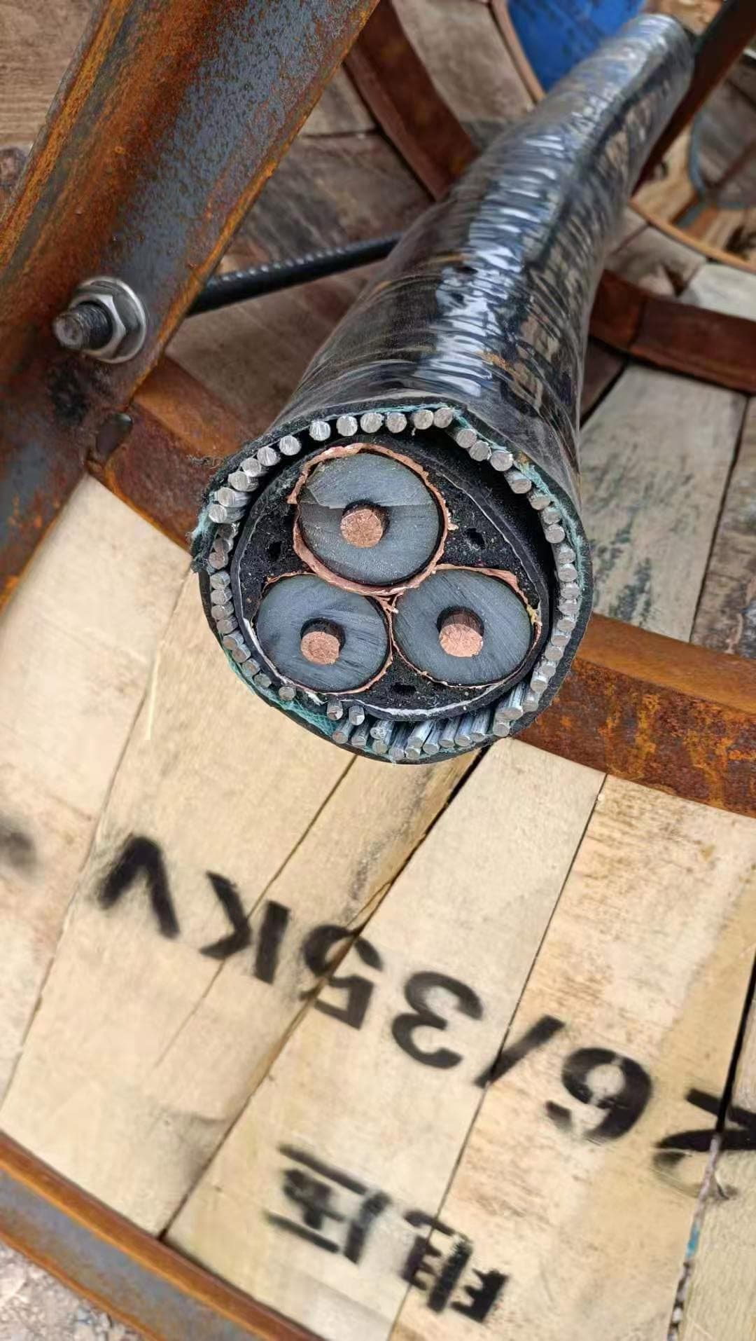
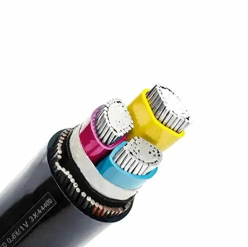
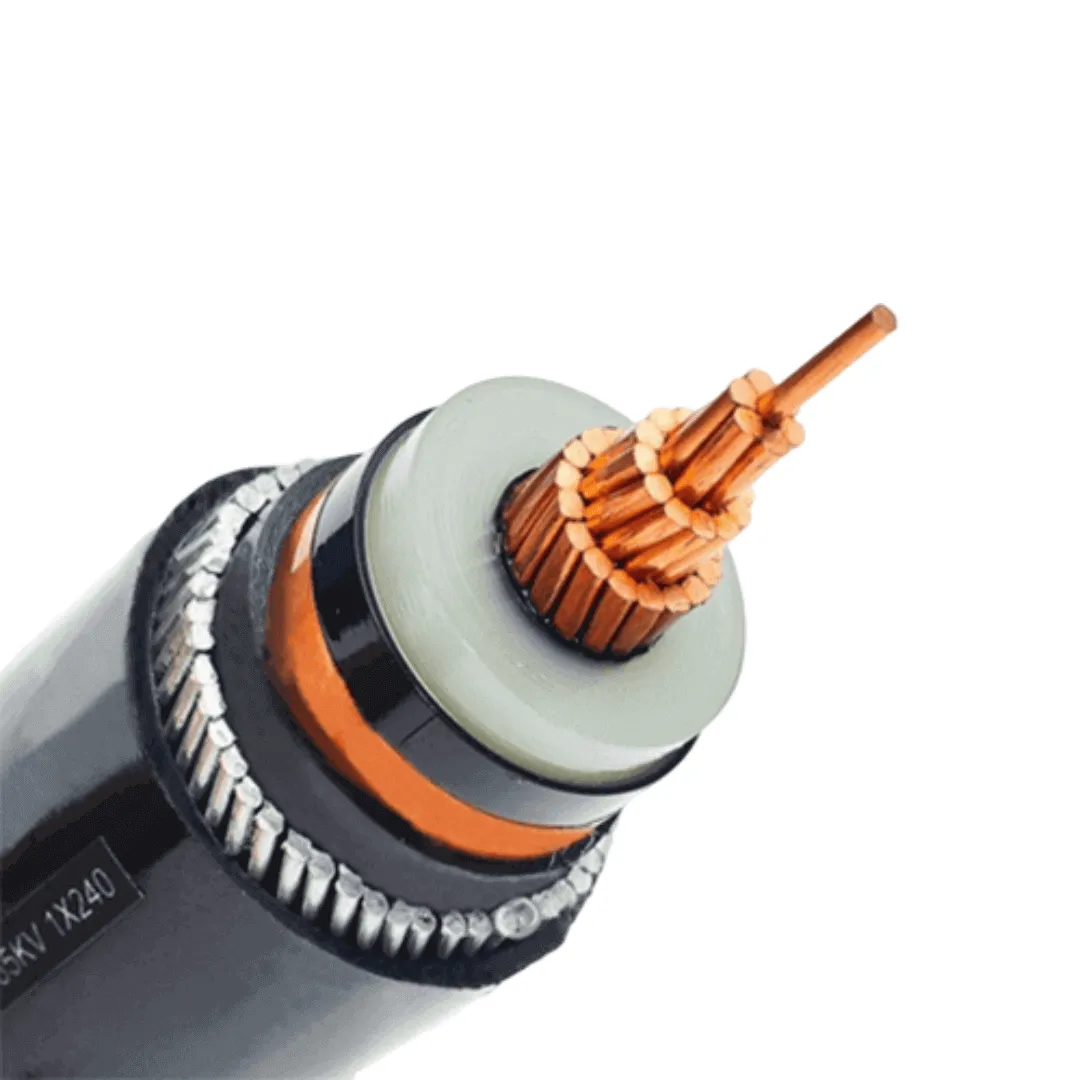
Steel Wire Armoured (SWA) cable is the standard choice for underground power distribution, outdoor installations, and any route where mechanical protection is required. However, the cable's performance and service life depend entirely on correct installation practice.
This guide covers every aspect of SWA cable installation — from trench preparation and burial depth requirements to cable gland selection, bending radius limits, earthing connections, and common mistakes that cause premature failure. All recommendations reference IEC 60502, BS 7671 (18th Edition), and BS 5467 standards.
Whether you are an EPC contractor installing distribution feeders across a solar farm, a project engineer specifying cable routes for a commercial development, or a facilities manager running power to an outbuilding — this guide provides the technical detail you need to install SWA cable correctly, safely, and in compliance with international standards.
What This Guide Covers
- Section 1: Pre-installation planning — route surveys, cable selection verification, and documentation
- Section 2: Burial depth requirements by standard (IEC, BS 7671, local regulations)
- Section 3: Trench preparation — dimensions, bedding materials, and cable laying procedures
- Section 4: Cable gland selection — CW, BW, E1W types and when to use each
- Section 5: Bending radius requirements by cable size
- Section 6: Earthing and bonding the steel wire armour
- Section 7: Cable termination and jointing
- Section 8: Testing and commissioning
- Section 9: Common installation mistakes and how to avoid them
- Section 10: FAQ
Section 1: Pre-Installation Planning
Successful SWA cable installation starts before any trench is dug. Proper planning prevents costly rework, ensures regulatory compliance, and protects the cable investment over its expected 30–40 year service life.
Route Survey and Cable Route Planning
Before installation begins, conduct a thorough route survey to identify:
- Existing underground services — gas, water, telecoms, other power cables. In the UK, request cable plans from the local Distribution Network Operator (DNO). Internationally, check with local utility mapping services.
- Soil conditions — rocky ground, high water table, contaminated land, or areas with aggressive soil chemistry (low pH, high sulfate) that may require additional cable protection.
- Road crossings — any point where the cable route crosses a road or heavy vehicle access route requires increased burial depth and mechanical protection (typically a duct or concrete surround).
- Future development — plan routes to avoid areas where future construction, drainage, or landscaping work might disturb the cable.
Cable Selection Verification
Before installation, verify that the cable sizing is correct for the actual installation conditions:
- Confirm the cable's current rating accounts for the actual installation method (direct buried vs. in duct)
- Verify thermal derating factors for soil thermal resistivity at the specific site
- Check that voltage drop calculations remain within limits (typically ≤4% for a final circuit, per BS 7671 Appendix 12)
- Confirm the cable specification matches the project's standard requirements (BS 5467, IEC 60502-1, or equivalent)
Documentation Requirements
Maintain the following documentation throughout installation:
- Cable route drawing with GPS coordinates or surveyed positions
- Burial depth log at regular intervals (every 5–10 meters)
- Cable drum numbers and manufacturer test certificates
- Photographic evidence of trench bottom, bedding, cable laying, and backfill stages
- Megger (insulation resistance) test results before and after backfill
- As-built drawings showing final cable positions relative to permanent reference points
This documentation is not optional — it protects you during disputes, enables future maintenance, and satisfies inspection requirements in most jurisdictions.
Section 2: Burial Depth Requirements
Burial depth is one of the most critical installation parameters. Insufficient depth exposes the cable to mechanical damage from future excavation, agricultural activity, or ground movement. Excessive depth increases installation cost without proportional benefit.
Minimum Burial Depths by Standard
Data sources: NJUG Volume 1 (Guidelines on the Positioning of Underground Utilities), ENA TS 09-1, IEC 60502-1 Annex A. Referenced by BS 7671:2018 Chapter 52 (Selection and Erection of Wiring Systems).
Key Points on Burial Depth
Measurement reference: Burial depth is measured from the finished ground surface to the TOP of the cable (not the bottom of the trench).
Additional depth for unarmoured sections: If the cable transitions to an unarmoured type at any point, increase depth by 150 mm or provide duct protection.
Local regulations override: Always check local municipal or utility authority requirements. Many Middle Eastern countries (UAE, Saudi Arabia, Qatar) specify minimum 800 mm under roads. African nations often follow BS or French NFC standards depending on colonial history — verify before installation.
Cable protection tile/tape: Regardless of depth, install cable protection tiles (concrete or plastic) or marking tape 150 mm above the cable. This provides a warning to future excavators before they reach the cable itself.
Burial Depth Under Roads — Special Requirements
For road crossings, best practice requires:
- Minimum 600 mm depth (750 mm preferred for major roads)
- Cable installed in a duct (typically 100 mm or 150 mm HDPE) — this allows future cable replacement without re-excavating the road
- Duct sealed at both ends with duct seal compound or mechanical seals to prevent water ingress and gas migration
- Concrete surround recommended for high-traffic roads (minimum 75 mm concrete all around the duct)
- Road reinstatement to highway authority specification (SROH in UK, local equivalent elsewhere)
Depth Derating for Cable Current Rating
Burial depth directly affects cable current-carrying capacity. The IEC 60287 reference conditions assume 800 mm burial depth. Shallower installation allows slightly higher current rating due to better heat dissipation:
Source: IEC 60287-2-1 Table 1, correction factors for laying depth.
For projects where current rating is marginal, the combination of burial depth and soil thermal resistivity correction can make the difference between a cable passing or failing its thermal design. Refer to our SWA cable sizing guide for complete derating calculations.
Section 3: Trench Preparation and Cable Laying
Trench Dimensions
Standard trench dimensions for SWA cable installation:
Bedding Materials
The cable must rest on and be surrounded by material free from stones, sharp objects, and debris that could damage the outer sheath. Acceptable bedding materials:
- Selected fine backfill — excavated material sieved to remove stones >10 mm
- Sharp sand — clean, graded building sand (most common choice)
- Cement-bound sand (CBS) — for routes under roads or where future protection is critical
- Pea gravel — acceptable but offers less conformity than sand
Do NOT use:
- Ungraded excavated material directly against the cable
- Crusite, crusher dust with sharp angular fragments
- Material containing organic matter (decomposes, creates voids)
- Frozen material (expands on thawing, creates uneven support)
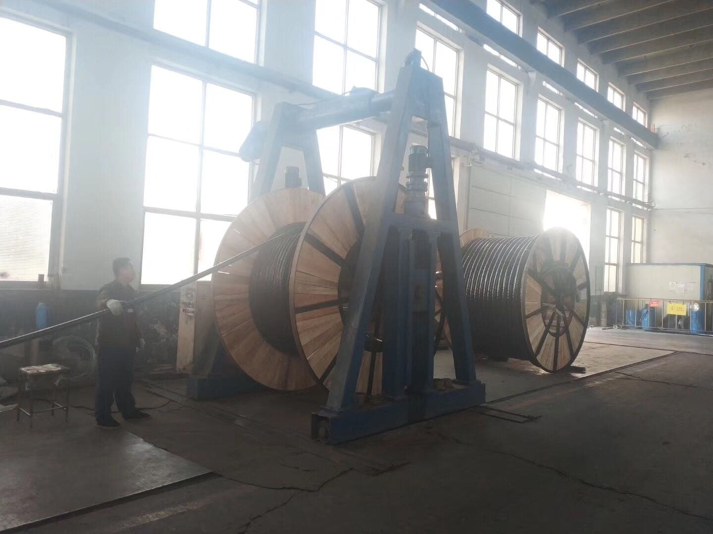
Cable Laying Procedure — Step by Step
Step 1: Trench Inspection
Before laying cable, inspect the full trench length:
- Bottom must be smooth, level, and free from protruding objects
- Bedding material evenly spread to specified depth
- No standing water (pump out if necessary)
- Trench walls stable (shore if deeper than 1.2 m for personnel safety)
Step 2: Cable Drum Positioning
- Position drum at one end of the route (usually the higher elevation end, so cable feeds downhill)
- Ensure drum can rotate freely on its spindle
- Check cable end for transport damage — cut back and discard any damaged length
- Verify drum label matches specification requirements
Step 3: Cable Pulling
For shorter runs (under 100 m):
- Manual pull with sufficient labor (never yank or jerk the cable)
- Use cable rollers at bends to prevent dragging on trench edges
- One person feeds cable off drum; others guide into trench
For longer runs (>100 m):
- Mechanical cable puller (winch) with calibrated tension gauge
- Maximum pulling tension = cable weight × coefficient of friction × route length. For SWA cable, typical maximum pulling force per cable manufacturer guidance:
- Up to 50 mm² conductor: 5 kN maximum
- 70–150 mm² conductor: 10 kN maximum
- 185–300 mm² conductor: 15 kN maximum
- Use cable pulling stocking (Chinese finger grip) on outer sheath — NEVER attach pulling equipment directly to conductors
- Maximum pulling speed: 15 m/minute to avoid thermal damage to sheath
Step 4: Cable Positioning in Trench
- Lay cable in gentle S-curves (snaking) to allow 1–2% slack — this accommodates ground settlement and thermal expansion
- At all bends, maintain minimum bending radius (see Section 5)
- Cables in flat formation: maintain uniform spacing with spacers or ties at 1–2 m intervals
- Cables in trefoil: bind with cable ties or tape at 1 m intervals
Step 5: Cover and Protection
- Apply 75–100 mm fine material cover above cable
- Place cable protection tiles (minimum 230 mm wide) or continuous cable protection strip above the covered cable
- Alternatively, place cable marker tape (yellow "ELECTRIC CABLE BELOW" tape) 300 mm above cable
- Both tile AND tape recommended for critical circuits
Step 6: Backfill
- Backfill in layers of 150–200 mm, compacting each layer
- First 300 mm above protection tiles: fine material only (no stones >25 mm)
- Remainder: selected excavated material acceptable if free from large rocks
- Compact to match surrounding ground density (avoid future settlement)
- Reinstate surface to original condition
Section 4: Cable Gland Selection — CW, BW, and E1W Types
The cable gland is the mechanical termination point where SWA cable enters an enclosure (panel, junction box, motor terminal box). Correct gland selection ensures:
- Mechanical cable retention (pull-out resistance)
- IP-rated seal against dust and moisture ingress
- Electrical continuity of the armour for earthing purposes
- Compliance with ATEX/IECEx requirements in hazardous areas (if applicable)
Cable Gland Types for SWA Cable
CW vs BW Glands — Decision Guide
Use CW glands when:
- Installation is indoors and dry
- IP rating requirement is ≤IP54
- Cable enters panel from below (gravity prevents water tracking)
- Cost sensitivity is high (CW glands are 30–40% cheaper than BW)
Use BW glands when:
- Installation is outdoors or in damp/wet locations
- Cable emerges from underground into surface-mounted equipment
- IP66/IP68 seal is required at the enclosure entry
- Cable route is exposed to rain, spray, or condensation
- The specification says "weatherproof gland" or equivalent
Use E1W glands when:
- Installation is in a classified hazardous area (Zone 1, Zone 2, Zone 21, Zone 22)
- ATEX or IECEx certification is required for the enclosure integrity
- The cable gland forms part of the Ex-rated barrier between hazardous and safe areas
- Additional flame path and seal is required per EN 60079-0/EN 60079-1
Gland Sizing
Cable glands are sized by the cable's overall diameter (OD), NOT by conductor size. Measure the actual cable OD with calipers before ordering glands.
Note: Always select the gland whose range spans the measured cable OD. If the cable OD falls between two gland sizes, use the larger size and compensate with the gland's internal compression ring.
Gland Installation Procedure
- Strip outer sheath — remove sufficient length to allow armour wires to fan out (typically 40–60 mm depending on gland size)
- Slide back-nut and body over the cable end before stripping
- Cut armour wires to length — they must sit within the armour clamp cone of the gland body
- Fan armour wires evenly around the circumference — 360° distribution ensures even clamping force and reliable earth continuity
- Assemble gland body — push cable into gland, seat armour wires into clamp ring
- Tighten compression nut — this clamps the armour and provides mechanical retention. Torque per manufacturer's specification (typically 30–60 Nm for larger glands)
- Attach lock nut inside enclosure — provides IP seal and prevents back-off
- Test pull-out resistance — standard requires the gland to resist a pull force of 10× cable weight per meter of vertical drop, minimum 100 N for small cables
Need SWA Cable for Your Installation Project?
China Cable Factory supplies SWA cable in all sizes from 1.5mm² to 300mm², manufactured to IEC 60502-1, BS 5467, and BS 6724. Contact our engineering team for cable selection assistance and factory-direct pricing.
Request QuoteSection 5: Bending Radius Requirements
Exceeding the minimum bending radius is one of the most common causes of cable failure. Overbending damages the insulation, deforms conductors, and can crack the armour wires — creating a weak point that fails under thermal cycling or ground movement over time.
Minimum Bending Radius for SWA Cable
Per IEC 60502-1 Clause 11 and cable manufacturer datasheets:
Source: IEC 60502-1 Clause 11.1. BS 7671:2018 Regulation 522.8.3 requires compliance with manufacturer-specified minimum bending radii.
Practical Bending Radius Examples
Bending Radius at Trench Changes of Direction
When the cable route changes direction in the trench:
- Gradual curves are preferred — lay the cable in a smooth arc, not a sharp corner
- If a 90° change is unavoidable, excavate a wider area at the bend point to accommodate the radius
- For large cables (OD > 40 mm), consider pre-formed bends or a larger chamber/pit at direction changes
- Never force a cable into a bend — if it resists, the bend is too tight
- At vertical bends (e.g., cable rising from trench to surface enclosure), support the cable with a smooth radius former or use a pre-bent duct
Signs of Overbending Damage
During installation, stop immediately and inspect if you observe:
- Visible kinking or flattening of the cable's circular profile
- Outer sheath wrinkling or whitening (stress marks in PVC/PE)
- Audible cracking sounds (armour wire fracture)
- Cable will not lie flat in the trench after bending (spring-back deformation)
Any cable section showing these signs should be cut out and discarded. Do not bury damaged cable — it will fail in service, potentially causing fire, electrocution, or costly excavation for replacement.
Section 6: Earthing and Bonding the Steel Wire Armour
The steel wire armour of SWA cable serves two purposes: mechanical protection AND circuit protective conductor (CPC). In most installations, the armour is used as the earth path back to the supply source. This is permitted under BS 7671 Regulation 543.2 provided the armour's cross-sectional area meets the minimum CPC requirements of Table 54.7.
Armour as CPC — Requirements
For the armour to function as the CPC:
- Electrical continuity must be maintained through every gland, joint, and termination point in the cable route
- Armour CSA must be adequate for the prospective earth fault current and disconnection time. Use the adiabatic equation: s = √(I²t) / k, where:
- s = minimum CPC cross-sectional area (mm²)
- I = prospective earth fault current (A)
- t = disconnection time (s) — per BS 7671, typically 0.4s for final circuits, 5s for distribution circuits
- k = material constant (k = 46 for steel at 160°C, per BS 7671 Table 54.4)
- Earth continuity test must confirm less than 1 Ω from cable armour at the far end back to the main earthing terminal
Armour Cross-Sectional Area (Typical Values)
Data source: BS 5467:1997 Table A.4, armour wire data for multicore SWA cables. Maximum fault current calculated using k=46, t=5s.
Earthing at the Cable Gland
The cable gland provides the primary earth connection between the cable armour and the enclosure:
- Gland must make 360° contact with all armour wires — this is why correct wire fanning and gland assembly is critical
- Earth tag (gland earth lug) must be fitted and bonded to the enclosure earth bar with a green/yellow conductor of adequate CSA
- Lock nut secures the gland and ensures metal-to-metal contact with the enclosure body (for indirect earthing path)
- Both ends of the cable must have armour bonded to earth — at the supply end AND the load end
Supplementary Earth Conductor
If the armour CSA is insufficient for the calculated fault current (typically for long runs or large circuits), install a supplementary CPC:
- Run a separate green/yellow earth conductor alongside the cable in the trench
- Bond this conductor to the armour at both ends and at intermediate joint positions
- Size per BS 7671 Table 54.7 or the adiabatic equation
Common Earthing Mistakes
- Single armour wire not clamped — one loose wire dramatically increases armour resistance. Ensure ALL wires are captured by the gland clamp ring.
- Corroded gland connections — outdoor installations must use glands with corrosion-resistant finishes (nickel-plated brass or stainless steel in aggressive environments)
- Earth tag not connected — the gland is mechanically complete but electrically isolated from the enclosure earth system. Always verify continuity after assembly.
- Armour continuity broken at joints — any cable joint must maintain armour continuity through the joint body. Use proprietary joint kits with integrated armour connectors.
Section 7: Cable Termination and Jointing
Termination at Panels and Enclosures
SWA cable termination involves:
- Outer sheath removal — strip back sufficient length for the gland assembly (40–100 mm depending on cable size). Use a cable stripping tool — do NOT use a knife that could nick armour wires or insulation.
- Armour wire preparation — cut wires to the required length for the gland type. File any sharp wire ends to prevent insulation damage.
- Bedding layer removal — strip the inner sheath (bedding) back to the point where individual cores need to separate and route to their terminals.
- Core identification — verify core colours match the circuit designation. Standard colours per BS 7671: Brown (L1), Black (L2), Grey (L3), Blue (N), Green/Yellow (E). For older cables: Red (L1), Yellow (L2), Blue (L3), Black (N).
- Core termination — use appropriate cable lugs (crimped, not soldered) for all conductors ≥10 mm². Smaller conductors may use ferrules or direct clamping depending on the terminal type.
- Torque connections — tighten all terminal connections to the panel manufacturer's specified torque value. Record torque values in the commissioning documentation.
Mid-Route Jointing
When cable route lengths exceed the maximum drum length (typically 500–1000 m depending on cable size), or when a cable is damaged and requires repair:
- Use a proprietary resin joint kit rated for the cable voltage and type
- The joint must maintain: insulation integrity, armour continuity, mechanical protection, and environmental seal
- Joint pits should be excavated larger than the trench (minimum 600 mm × 600 mm × depth) to allow working space
- Record joint positions on as-built drawings with GPS coordinates
- Consider installing a joint chamber (precast concrete pit with cover) for maintenance accessibility
Note: Every joint is a potential failure point. Minimize joints wherever possible — order cable in maximum available drum lengths to reduce joint count.
Section 8: Testing and Commissioning
Pre-Energisation Tests
All tests must be performed by a competent person using calibrated instruments. Record all results on the appropriate test certificate (BS 7671 model forms or equivalent).
Test 1: Visual Inspection
- Verify correct cable type and size installed
- Check all glands are tight and earth tags connected
- Confirm cable route markers and protection tiles in place
- Inspect for visible damage to outer sheath
Test 2: Continuity of Protective Conductors (R1+R2)
- Test continuity of cable armour from source to load end
- Expected result: low resistance proportional to cable length. For steel armour, typical values are 1–5 Ω per km depending on armour CSA.
- Test continuity of earth tag bonds at each gland
Test 3: Insulation Resistance (Megger Test)
- Test voltage: 500 V DC for cables rated ≤500 V; 1000 V DC for cables rated 600/1000 V
- Test between each conductor and earth (armour)
- Test between each pair of conductors
- Minimum acceptable value: 1 MΩ (BS 7671 requires >1 MΩ; new cable should read >100 MΩ)
- Perform BEFORE backfill — if a fault is found, the cable is still accessible
- Repeat AFTER backfill — confirms no damage occurred during backfill operations
Test 4: Earth Fault Loop Impedance (Zs)
- Measure or calculate to confirm automatic disconnection of supply will occur within the required time
- Compare measured Zs with maximum values from BS 7671 Table 41.2/41.3/41.4
Test 5: Prospective Fault Current (PSCC)
- Measure at the far end of the cable
- Confirm that switchgear/protective devices at both ends have adequate breaking capacity
Commissioning Documentation
Complete the following before the cable is declared fit for service:
- Electrical Installation Certificate (EIC) or Minor Works Certificate as appropriate
- Schedule of Test Results with all measured values
- Cable test certificates from manufacturer (routine test results from factory)
- As-built route drawings
- Photographic record
- Operation & Maintenance manual (if part of a larger installation)
Section 9: Common Installation Mistakes and How to Avoid Them
Mistake 1: Insufficient Burial Depth
What happens: Cable is damaged by future excavation (digging for drainage, landscaping, new services).
How to avoid: Measure depth at multiple points during trench inspection. Use a depth gauge. Record measurements in the depth log. Never accept "it looks deep enough" — measure.
Mistake 2: No Cable Protection Tiles or Tape
What happens: Future excavators hit the cable without warning. Even at correct depth, mechanical excavators can dig through 600 mm of soil in seconds.
How to avoid: Always install protection tiles (preferred) or marking tape. Budget for this — it is not optional. Cost is negligible compared to a cable strike.
Mistake 3: Exceeding Bending Radius
What happens: Insulation cracking, armour wire fracture, eventual cable failure (often months or years after installation, making the cause difficult to identify).
How to avoid: Pre-calculate minimum bend radius for your cable size. Mark it on site. Use cable rollers at bends during pulling. If in doubt, make the bend wider.
Mistake 4: Wrong Gland Type for Environment
What happens: Water ingress at gland entry point, leading to insulation degradation, corrosion of armour, and eventual earth fault.
How to avoid: Use BW glands for any outdoor or damp location. Use E1W for hazardous areas. Never use indoor-rated CW glands outside.
Mistake 5: Armour Not Properly Earthed
What happens: Under fault conditions, the armour cannot carry fault current safely. This may result in:
- Protective device failing to operate (or operating too slowly)
- Armour overheating and igniting cable/surrounding material
- Dangerous touch voltages on metalwork
How to avoid: Test armour continuity at every gland. Verify earth tag connections. Record R1+R2 values. Retest annually for critical circuits.
Mistake 6: Cable Pulling Damage
What happens: Excessive tension stretches or tears the outer sheath. Conductor elongation exceeds elastic limit, increasing resistance. Armour wires displace or fracture internally.
How to avoid: Use calibrated tension monitoring. Never exceed published maximum pulling tensions. Use sufficient cable rollers. If the cable "jams" — stop, investigate, and clear the obstruction. Never increase pulling force to overcome a snag.
Mistake 7: Backfill with Sharp Material
What happens: Stones or broken concrete press against the cable under ground pressure. Over years, vibration from traffic works the sharp edges through the outer sheath. Eventually, moisture reaches the armour and insulation.
How to avoid: Specified bedding material (sand or fine fill) for the 150 mm envelope around the cable. Inspect backfill material visually. Remove stones >10 mm from the immediate cable zone.
Mistake 8: No Slack in the Cable
What happens: Ground settlement or thermal expansion/contraction puts the cable in tension. This stress concentrates at gland entries and bends, eventually causing sheath cracking or conductor fatigue.
How to avoid: Always lay cable with 1–2% slack (gentle S-curves). At vertical rises, provide a drip loop. At entries to fixed equipment, leave a service loop for future re-termination.
Section 10: Frequently Asked Questions
How deep should SWA cable be buried?
Minimum 450 mm under footpaths, 600 mm under roads, and 750 mm under agricultural land. These figures are per NJUG Volume 1 and ENA TS 09-1 guidelines, referenced by BS 7671 Chapter 52. Always check local regulations — some Middle Eastern and African markets require 800 mm minimum under roads. Depth is measured from finished ground level to the top of the cable.
Can SWA cable be buried directly without a duct?
Yes. SWA cable is specifically designed for direct burial — the steel wire armour provides mechanical protection against impact, compression, and rodent damage. However, installing in a duct is recommended at road crossings (for future replacement access) and in areas where future excavation is likely.
What type of cable gland should I use for outdoor SWA installation?
Use a BW (outdoor/weatherproof) gland for any outdoor or damp location. BW glands provide an IP66/IP68 environmental seal at the cable entry point. CW glands are only suitable for dry indoor environments. For hazardous areas (petrochemical, mining), use E1W barrier glands with appropriate ATEX/IECEx certification.
What is the minimum bending radius for SWA cable?
For multicore SWA cable with overall diameter ≤25 mm: 6 × cable OD. For multicore SWA cable with OD >25 mm: 8 × cable OD. For XLPE-insulated SWA cable (all sizes): 8 × cable OD. During cable pulling, add 50% to these values. See Section 5 for practical examples by cable size.
Can the SWA armour be used as the earth conductor?
Yes. Per BS 7671 Regulation 543.2, the steel wire armour can serve as the circuit protective conductor (CPC) provided its cross-sectional area is adequate for the prospective earth fault current and disconnection time. Verify using the adiabatic equation s = √(I²t) / k. For long runs or high fault currents, a supplementary earth conductor may be needed alongside the cable.
How do I calculate the maximum pulling tension for SWA cable?
Maximum pulling tension depends on conductor size and is specified by the cable manufacturer: up to 5 kN for conductors ≤50 mm², up to 10 kN for 70–150 mm², and up to 15 kN for 185–300 mm². Always use a cable pulling stocking (not attached to conductors) and monitor tension with a calibrated gauge. Maximum pulling speed should not exceed 15 m/minute.
What bedding material should surround buried SWA cable?
Clean, sharp sand or fine selected backfill (stones removed >10 mm) for a minimum 75 mm envelope around the cable. Do not use ungraded excavated material, crusher dust with angular fragments, or material containing organic matter. For road crossings, cement-bound sand (CBS) provides superior mechanical protection.
How do I joint two lengths of SWA cable underground?
Use a proprietary resin joint kit rated for the cable voltage class (typically 0.6/1 kV for LV SWA). The joint must maintain insulation integrity, armour continuity, mechanical protection, and environmental seal. Record joint positions on as-built drawings. Minimize joints wherever possible by ordering cable in maximum drum lengths.
What testing is required after SWA cable installation?
At minimum: visual inspection, continuity of protective conductors (armour), insulation resistance (Megger test at 500 V or 1000 V DC), earth fault loop impedance (Zs), and prospective fault current (PSCC). Insulation resistance should be tested before and after backfill. All results must be recorded on the appropriate test certificate.
How long does SWA cable last when buried underground?
With correct installation (proper bedding, adequate depth, no mechanical damage), SWA cable has a design life of 30–40 years in typical soil conditions. Factors that reduce cable life include: aggressive soil chemistry (high sulfate, low pH), persistent waterlogging, thermal overload, and mechanical damage from ground movement or third-party excavation. Regular insulation resistance testing (every 5–10 years) can identify degradation before failure occurs.
Internal Resources
For more detailed information on related aspects of SWA cable selection and procurement:
- SWA Cable Price Per Meter: 2026 Factory Cost Guide & Bulk Rates — Pricing breakdown by size, material, and order volume
- SWA Cable Sizing Guide: Current Ratings & Voltage Drop (1.5–300mm²) — Complete sizing methodology with derating tables
- SWA Cable: Sizes, Current Rating & Supplier Guide — Full product specifications and factory capabilities
- Armoured Cable Manufacturer & Supplier — Complete range of armoured cable options
- Underground Power Cable Types & Installation — Broader guide covering all underground cable types
- 4-Core Armoured Cable: SWA vs STA Specifications — Detailed comparison of wire and tape armour
- Armoured Cable vs Non-Armoured: When to Use Each — Decision framework for cable selection
Get Factory-Direct SWA Cable for Your Project
Huanghe Cable manufactures SWA cable from 1.5mm² to 300mm² in 2-core, 3-core, 4-core, and 5-core configurations. All cables produced to IEC 60502-1, BS 5467, and NFC 33-226 standards with independent test certification. Minimum order 500–1,000 m per size.
Request Installation Project Quote